Showing posts with label divergence reshaping. Show all posts

Friday, February 28, 2014

Is beam-shaping necessary?

A Fresnel Veselago lens, without any beam-shaping, can produce an annular focal zone of modest concentration from a solar highbeams field.

Beam-shaping (reshaping divergence) at the Fresnel Veselago lens can potentially produce very high concentration at the oculus—and thus reduce thermal losses from the hot space—but this would come at a cost of complexity and reflection loss. Is this a marginal improvement we could postpone for later?

Since reflection losses in beam-shaping with lenticular lens arrays will probably subtract at least of 5% of the total power, and improving concentration at the oculus by a factor of four would reduce the radiant heat percentage, q, by the same factor, the improvement offered by beam-shaping is something like

0.75q - 0.05.

Assuming we would put off for now a 10% improvement in system power in the interest of simplification, that is, if:

0.75q - 0.05 < 0.1,

or q < 20% .

Radiant flux in the hot space at the 3/4-full temperature of 1936 °K is 800 suns (calculations included in the figure above too-generously assume radiant transfer at the empty temperature of 1250 °C = 1523 °K) this becomes a 20% loss when the incident flux is 4,000 suns. From the diagram above it looks like that is probably about four times more concentration than can be achieved at an annular focal zone without divergence reshaping. Adding a 2D CPC concentrator to the annulus or 2D radiation traps for thermal radiation escaping at wide angles might effectively double the concentration at the annulus to 2,000 suns, but that would still leave us a factor of two away, and we would really rather be at 8,000 suns so that heat loss is reduced to 10%.

A better approach is to bring light directly to a circular focal zone. Calculations in the diagram suggest we can get above 3500 suns without beam-shaping, and additionally we can  block much of the radiant heat loss by suspending an elliptical mirror over the oculus. (Sunlight is shown directly striking the boiler tubes, but this could be avoided by slanting the tubes, arranging them on the inside of a cone rather than a cylinder.)


A Fresnel Veselago lens, without any beam-shaping, can produce a circular focal zone with high concentration.

Is beam-shaping necessary? Likely not.

Sunday, November 17, 2013

Divergence rotation

Every centroid-coordinated tessellation of circles and ellipses (left) can be affine-transformed into a centroid-coordinated tessellation of ellipses that are identical but rotated 90° (right.)

A special case of divergence reshaping occurs when the new divergence pattern actually has the same shape, but is oriented differently.

Any coordinated tessellation of circles and ellipses can be transformed by affine transformation into a design for a divergence reshaper that rotates an incident elliptical beam 90°. If the ellipses in the coordinated tessellation have aspect ratio A, an affine shrinking of both circles and ellipses in the direction of the major axis of the ellipses by √A, yields a coordinated tessellation of identically shaped ellipses, all of aspect ratio √A, lying at right angles to each other.

From the previous result that hexagonally-packed coordinated tessellations of circles and ellipses exist for aspect ratios drawn from the central polygonal numbers, {1, 3, 7, 13, 21, 31, 43, 57, 73, 91…}, the magic aspect ratios for a tessellation of hexagonally-packed ellipses that can centroid coordinate with a 90° rotation of itself are the square roots of the central polygonal numbers, {√1, √3, √7, √13, √21, √31, √43, √57, √73, √91…}.

Another way to rotate the divergence pattern of a beam by 90° is to reflect it in a planar Rabl mirror, placing the dihedral line of the mirror at 45° to the major axis of the incident and rotated beams.

Cross-section of a planar Rabl mirror (3M prismatic film.) Image quoted from K.G. Kneipp, "Use of prismatic films to control light distribution."

A divergence rotating mirror: the divergence of a beam of light is rotated 90° by normal reflection from a Rabl prismatic mirror when the prisms'  dihedral lines lie at a 45° angle to the principal axes of the incident—and, as well, the reflected—beams.

Thursday, November 14, 2013

Divergence reshapers

A pair of lens arrays can constitute a divergence reshaper.

Arrangements of lens arrays (a.k.a., micro lenses, mini-lenses, lenslets, fly's eye lenses, lenticular arrays) like the one in the image above are known in beam homogenization and integral field spectroscopy. Though the relation between the two lens arrays is actually reciprocal, the first-encountered array is usually termed the field lens array, and the second-encountered array is usually termed the pupil lens array. Each lens array lies in the focal plane of the other, and the reciprocal system works equally well in both directions.

In some applications both arrays have lenses of the same planform, usually either rectangular or hexagonal. However, it is not necessary for both arrays to have lenses of the same planform: the centroid-coordinated tessellations of the plane indicate an infinity of other possibilities. When the two arrays differ in planform, the arrangement can be used to reshape the divergence of a beam of light.

A micro array of lenses having hexagonal planform. Image quoted from Anteryon.com.

In solar energy applications, in order to reduce energy losses, it is advantageous to make both lens arrays plano-convex and cement the two plano surfaces together, or to simply mold the whole apparatus out of one piece of glass or plastic. Since the focal lengths of both arrays are the same, the radius of curvature of the lenses in both arrays must be the same. In effect, all the lenslets are portions of spheres of the same radius.

The lenslets in the two arrays need not have the same planform for their centers to align. Here, lenslets of circular planform align with lenslets of elliptical planform.

For perfect imaging, the curvature of the field should also have the same radius. A well-known solution to this problem exists, one that is used in the design of spherical retroreflectors. When spheres have refractive index 2, they focus light from a distant source onto their own rear surface. This arrangement has spherical aberration, but the f-numbers needed for divergence rotation in solar energy applications are small. The lenslets on each face have dimensions that are small compared to the focal length, so the effect of spherical aberration is slight.

An integrated array of cat eye lenses (refractive index = 2) can serve as a divergence reshaper if the planforms of the lenses on each face differ. 


The small f-numbers also mean that refractive indices less than 2 can also be used with tolerable results, and that defocussing due to chromatic dispersion over the wide solar spectrum is not too severe.


Optical diagram of a divergence reshaper having refractive index 1.5. Incident light strikes the new side. If the incident beam has a maximum divergence of 15°, lenslets on the old side will be shaped in planform like the divergence of the original beam, and will have an f-number  of 5.8 based on their maximum dimension. 
In a divergence reshaper, the light strikes the new side—the side whose lenses are shaped in planform like the new divergence pattern. Light exits from the old side—the side whose lenses are shaped in planform like the old divergence pattern.

Monday, November 4, 2013

Centroid-coordinated tessellations

Inequivalent affine transformations can produce identical results when they act on an array of unlabeled points. In this case, shear plus one-dimensional magnification (not show) acts like the identity transformation.

Coordinated tessellations occur in two practical problems that arise in relation to telescopic heliostats: first, the problem of simultaneously packing the primary mirrors (as seen from the sun) and the secondary mirrors (as seen from the beam-down optics;) and second, the problem of simultaneously packing the primary and secondary lenses in the divergence reshapers that are a necessary part of the beam-down optics.

Definition: Two tessellations of the plane are centroid-coordinated when they are overlain such that each tile has its centroid coincident with that of a tile in the other tessellation.

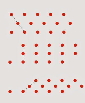
Non-trivial centroid coordination (when the two tessellations are not identical) is possible because, when acting on an array of unlabeled points (like the tile centroids of a tessellation,) inequivalent affine transformations may act identically. In other words, if we apply two inequivalent affine transformations to a tessellation we will generate two different tessellations as a result, but applying the same two transformations to an array of unlabeled points (e.g., the tile centroids) may give identical results.

For example, consider a set of tile centroids that are arrayed in a brick-layer's "stretcher bond" pattern as in the top arrangement in the figure above. Shearing this array of points takes them out of proper stretcher bond order (middle arrangement)—but shearing them some more can bring them back into a new stretcher bond order (bottom arrangement.) The height of the bricks is now too short, but that is easily corrected by composition with another affine transformation that is a magnification in one dimension only. This newly contrived composite transformation and the identity transformation now act identically on the array of tile centroids, but differently on the tessellation. The two tessellations generated by the transforms are centroid-coordinated.

The shearing-plus-magnification transform we need is just a shearing in which only x-coordinates are altered. The magic angles that work for this shearing, are ones for which dots translate in the x-dimension by an integer multiple, n, of the inter-dot distance, d.

For the stretcher bond pattern with shearing angle θ:

(d/ √3) * tanθ = n * d,

tanθ = n √3.


For the Cartesian grid pattern

d * tanθ = n * d,

tanθ = n.


Rectangle tesellations


A centroid coordination of a tessellation of squares with a tessellation of 4:1 rectangles. In this kind of arrangement, the centroids are arranged along oblique lines that rise one rectangle's height in traveling the other rectangle's width. Both kinds of rectangles have the same area.

When two rectangle tessellations, a and b, are centroid coordinated, their heights, ha and hb, and widths, wa and wb, are related by two integers, m and n. Taking the rectangles of type a to be the taller, and those of type b the wider:

ha = m hb

wb = n wa.

But the rectangle areas are equal:

ha * wa = hb * wb

so,

m hb * wa = hb * n wa

m = n.

This is just the commonsense notion that, if two rectangles have the same area, and one is a factor f times taller, it must also be a factor of f times narrower. For rectangles in centroid-coordinated tessellations the constraint is added that f must be an integer.

Since the affine transformation of a polygon’s centroid is the centroid of the affine transformation of the polygon, once we have found a pair of centroid-coordinated tessellations, applying an affine transformation to both will generate a new pair of centroid-coordinated tessellations. For centroid-coordinated rectangle tessellations, their integer characteristic m is not altered by affine transformation, but we can vary the size and aspect ratio one species of rectangle just as we please by choosing different values of linear magnification in each dimension.

For example, we can choose an affine transformation that turns one species of rectangles into squares. Therefore, every pair of centroid-coordinated rectangle tessellations is related by an affine transformation to another pair of centroid-coordinated rectangle tessellations having the same value of m, but where one species of rectangles are squares and the aspect ratio of the other species of rectangles is m squared.

For example, in designing a divergence reshaper having optical inputs and outputs that are delimited by solid angles of rectangular shape, if the output solid angle must be square in shape, the input solid angle must be a rectangle of aspect ratio m2, where m is an integer.

Friday, October 25, 2013

Beam-down optics for telescopic heliostat arrays

The focal zone of an array of telescopic heliostats scaled to 140 m height—yielding about 750 MWe.

Save for the intervention of the beam-down optics, light from a field of telescopic heliostats would converge onto a focal zone shaped something like an ice cream cone (the orange region in the figure above.)

Taking parameters from an earlier post:

Height to top of the beam-down optics: 140 m
Field radius: 1085 x 1.59 = 1725 m
Beam divergence: 3°
Angular elevation of beam center = 1.6° + 1.5° = 3.1°
[For comparison: the height of the Washington Monument is 169 m (152 m to the base of the pyramidal cap); the distance between the monument and the U.S. Capitol is 1800 m. The Capitol's dome is 88 m in height and 29 m in diameter.]
If it received only light from the outermost ring of heliostats, the focal zone would be a sphere centered at 1725 m x tan(3.1°) = 93 m high, with a radius of 1725 m x tan(3°) / 2 = 45 m. That is the "ice cream" at the top of the cone; superimposing many smaller and lower spheres for each ring of heliostats yields the "cone" itself. 

The beam divergence of a 6x telescopic heliostat (the pink spot) drawn as an area on the globe.

The beam divergence found near the center of an array of telescopic heliostats. Divergence has increased in longitude, but not in latitude.

We will describe the directions light propagates in by reference to an earth globe oriented with north pointing up, and with the prime meridian facing the heliostats we are concerned with. So, for example, close to the heliostat, the light lies within a circle 3 degrees in diameter that is centered on 0 degrees longitude and 3.1 degrees S latitude (the top picture above.) Closer to the focal zone, the light will have the same latitudinal extent, but its longitudinal extent will have increased because the light of many heliostats is being concentrated along that dimension (lower picture above.) The exact longitudinal extent can be calculated by taking a look in the opposite direction and calculating the angular subtense of the cone-shaped focal zone.

At times we need to know the divergence of light where the beam-down optics are located. We can get the same answer by reversing the light rays and considering the focal zone—rather than the heliostats—as the source of light.

Some considerations in designing beam-down optics:
  1. Placing beam-down optics too close to the focal cone will make the incident light too widely spread out in the longitudinal direction to be handled efficiently by the optics.
  2. We want the surface normal of the beam-down structure to make roughly equal angles with the incoming and outgoing light. This will avoid the same thermodynamic "gotcha" that afflicts conventional heliostat fields that direct high sun to a low target. 
  3. We want the incident light to cover the same area on the globe (i.e., subtend the same solid angle) as the opening of the furnace, because that is what we can do most efficiently, reshape, not resize, divergence. 

Wednesday, October 23, 2013

Reshaping divergence with lenslet arrays

Two lenslet arrays, separated by one mutual focal length, can be used to reshape the divergence of a light beam.

Optics near the central focus of a solar plant operates at high energy flux, for example, at the beam-down optics of a glass-making solar furnace the flux will be on the order of 100 suns. This creates both the need to operate at high optical efficiency, and the opportunity to employ more expensive optical solutions than are possible on surfaces of larger area.

Each point on the beam-down optics of a solar furnace will see the circular opening of the furnace (because it is distorted by perspective) as approximately an ellipse. The beam-down optics needs to redirect approximately horizontal radiation coming from the field of telescopic heliostats downward toward the furnace opening. It also needs to reshape the divergence of the radiation to fit inside the approximately elliptical angular extent of the furnace opening.

A simple way to reshape divergence is with two lenslet arrays of the same focal length, separated by one focal length. In effect, each array acts as a field lens for the other. As the figure above illustrates, the lenslets in the two arrays do not have to have the same shape (though they must have the same area) in order to be in perfect correspondence with the lenslets in the other array. For example, in the figure above, circularly divergent light entering through the elliptical lenslets, would exit the round lenslets with elliptical divergence.