Friday, January 31, 2014

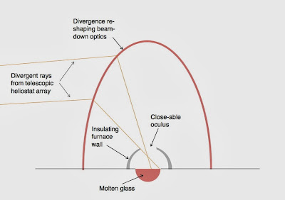
Scaled generations of all-glass, glass-making solar furnaces


Specifications for scaled generations of all-glass, glass-making solar furnaces.

A classic science-kid's demonstration is making glass from sand with a solar furnace, and, in fact, the glass-making capacity of a solar furnace is prodigious. A solar furnace of any size, even if it is 100% glass, can make all the glass needed to replicate itself in a matter of weeks. The glass replication time of a small backyard solar furnace may be only a matter of days. More likely at large scale, the glass for a furnace would be produced by a smaller solar furnace that produces at a rate that does not outstrip the capacity to fabricate and assemble glass parts. That smaller furnace, in turn, may have been made by an still smaller furnace; and so on, through multiple generations of scale.

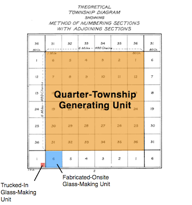
Starting at a very big scale (a solar furnace on 9 square miles of land) and working for the most part within areal units of the Public Land Survey System of the western United States, the table above shows specifications for six scaled generations. If these calculations can be taken seriously, the time from the completion of the room-sized 9-square meter furnace to the completion of its descendant quarter-township furnace is 6.3 years.

Thursday, January 30, 2014

Reproduction times and mass flows for all-glass, glass-making solar furnaces

All-glass, glass-making solar furnaces can be built up starting from a small seed.

When we tap power from a solar furnace (which is really what CSP power towers are,) we are tapping power from a thing that can make other things. When the day comes that solar furnace energy is cost competitive with coal for boiler-temperature heat, it will already be a factor of two or three times cheaper than any other source of high-temperature heat for making things. The economics of certain materials will be revolutionized by the availability of cheaper high-temperature heat, none more so than glass.

Laurent Pilon et al. studied thermal transfer in a glass-making furnace that produced 3.35 kg/s of soda-lime glass, with a heat transfer from the combustion space to the melt of 8.3 MW. Thus the energy intensity of this portion of the glass making process is (8,300,000 J/s) / (3.35 kg/s) = 2.5 E6 J/kg. The room temperature density of soda-lime glass is 2600 kg/m3, so, ignoring additional heat requirements in the annealing, the energy intensity of finished glass is 6.4 E9 J/m3.

The solar generating unit Ivanpah 1, produces 126 MWe at a 32% capacity factor, thus averaging 40 MWe over the course of 24 hours. At a conversion efficiency of 0.40, Ivanpah 1 must be producing thermal power of 40 MWe / (0.40 MWe/MWth) = 100 MWth = 1.0 E8 J/s .

Therefore, Ivanpah 1, relieved of its power-generating duties, could make glass at the rate of (1.0 E8 J/s) / (6.4 E9 J/m3) = 0.016 m3/s or 16 liter/s.

Ivanpah 1 has 53,527 heliostats each with a mirror area of 15 m2, giving a total mirror area of 803,000 m2.

Now comes the guessing part: if a solar furnace is made entirely of glass, and the total volume of glass is pro-rated to the heliostat mirror area, how thick will the layer be? I'm going to say 5 cm (0.05 m.) On that basis, in making the glass for an Ivanpah 2, Ivanpah 1 must make (.05 m) * (803,000 m2) = 40,000 m3 of glass.

At 16 liter/s (0.016 m3/s), that task will occupy Ivanpah 1 for (40,000 m3) / (0.016 m3/s) = 2.5 E6 s = 700 h = 29 days.

Making the glass for two copies of itself, an all-glass Ivanpah 1 solar furnace would be offline for just two months! (Of course there's a lot more to it than just making glass, but that other stuff is not Ivanpah 1's responsibility.)


Suppose each solar furnace makes the glass for two copies of itself and only afterwards gets about the business of full-time power generation. The glass for two units can be made in 2 months, but completing them will take longer, let's say it takes an additional 10 months. Setting the year clock to n = 0 when the first solar furnace starts making glass, and taking a census of solar furnaces annually, the census series will be:

1, 3, 7, 15, 31, 63, 127, 255, 511…  =  2n+1 - 1

Replicating to 300 units takes less than 8 years.


That said, it might make more sense to do things the old-fashioned way, using a special-purpose solar furnace sited near the best raw materials. An individual glass-making unit would need 300 months (25 years) to make glass for 300 units, so 3 specialized glass-making furnaces would be needed to make 300 units in about 8 years.

The quarter-township units proposed in an earlier post are considerably larger than Ivanpah 1, their thermal power is

(1000 MWe) * ( 0.75 capacity factor) / (0.40 MWe/MWth) = 1875 MWth,

which is comparable to the thermal power of a 1 GWe coal-fired plant.

That is 1875 / 100 = 19 times more thermal energy than Ivanpah 1 produces, so it yields 19 * 16 l/s  =  300 liters of glass per second. If the glass layer thickness (0.05 m) is the same, the reproduction time will be the same as calculated above (4 weeks), but the mass flows are huge: 2,800 tons of glass per hour, 24/7. Put in terms of the 120-ton capacity of one railroad coal car, that would be 570 cars—or about five, 120-car unit trains per day. That is a mass flux is needed in two directions, carrying materials in and glass parts out.


Such big mass flows need to be as short as possible. A "growing from an acorn" motto seems more appropriate than "dividing like yeast." Since a small unit can make in three years the glass for a unit 36 times larger than itself; and, since solar resource quality varies gradually over wide areas; it makes sense to site a relatively small, specialized glass-making unit where raw material resources are excellent, and let it slowly build the larger specialized power-generating unit. When the local area is considered built-out, the glass-making unit might be disassembled and relocated, or retired in-place to making spares.

To make a quarter-township solar generating unit, a one-section (one square mile) solar glass-making unit would need 9 months to make the glass; a quarter-section solar glass-making unit would need 36 months. Since it usually takes 3 to 4 years to build a conventional power plant, a quarter-section glass-making unit is probably about right.

The quarter-section glass-making unit could itself be built in 16 months by a 10-acre glass-making unit. If fabrication and assembly proceed just-in-time with the glass production, a quarter-township generating unit would be completed in 16 + 16 + 36 = 68 months (5.7 years) after the 10-acre unit starts producing glass.

In this way, the maximum mass flow, which occurs during the 36 months when the quarter-section glass-making unit is making parts for the quarter-township generating unit, amounts to 570/36 = 16 rail cars per day, but these trips are from local quarries and out to the adjoining, under-construction, heliostat field.

If the 10-acre (40,470 m2) unit can be slimmed down to a 2.5 cm glass layer—say, by using half-scale heliostats—then its mass is

40,470 m2 * (0.70 mirror/land ratio) * (0.025 m) * (2600 kg/m3) = 1800 tons

amounting to 15 rail cars to deliver it ready-to-assemble.

As a check: the trucked-in plant would make that much glass (15 rail cars) in just 2 weeks (being a slimmed-down, half-thickness design), so it can make about 1 rail car per day of glass. After successive multiplications of 16x (going up to a quarter-section, or 160 acres) and 36x (going up to a quarter-township, or 9 sections) the yield of the quarter-township unit should be (1 railcar/day) * 576 = 576 railcars/day, which checks against 570 rail-cars calculated above.

If it is necessary to reduce the freight still more, another factor of 16, down to a 2500 m2 land area (50 m x 50 m,) would just add 8 more months (since slimmed-down units replicate in just half a month.) The trucked-in weight now down to 110 tons. Another factor of 16, down to a 160 m2 land area (13 m x 13 m,) would add 8 months and reduce freight down to one load for a medium duty truck, 7 tons.




The Veselago lens, transflection, and negative-one refractive index (nori) optics

Optical diagram of a single-interface Veselago lens. Image quoted from Yee Sin Ang et al., "Retro reflection of electrons at the interface of bilayer graphene and superconductor."

I just learned of the Veselago lens, an imaging application of negative-one refractive index. The diagram above shows the simplest case, a single refractive index interface producing a real image: in fact, every object in ni will have a real image in -ni, and vice-versa. Uses of the Veselago lens (typically with two interfaces, as shown below) are being actively investigated by nano-materials scientists interested in genuinely propagating waves in a negative index medium. As we have seen, such is not necessary in solar power optics, if the divergence pattern has the right symmetry, a Fresnel mirror with its facets tilted 90° has optics identical to an ni/-ni interface.

Optical diagram of a two-interface Veselago lens. Image quoted from Lukas Novotny, "Principles of Nano-Optics."


It is helpful to look at the Veselago lens from all four perspectives: retroflection, transmission, reflection, and transflection. If a room has a retro-reflective plane instead of a window, light will be returned directly back to each object in the room, forming a real image that happens to coincide in every case with the object itself, and thus has the same handedness. If there is indeed a transmissive plane where the window should be, an observer on the outside perceives a virtual image that happens to coincide in every case with the object itself, and thus has the same handedness. If there is a mirror (reflective plane) where the window should be, there is virtual image of the room (turned inside-out) in the space outside, and thus handedness is reversed. If there is a transflective plane (or equivalently, the ni/-ni interface of a Veselago lens) there is a real image of the room (turned inside-out) in the space outside, and thus handedness is reversed.

Life after Coal

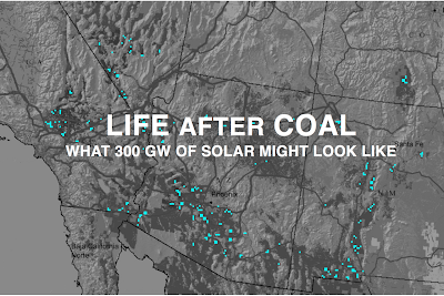
Life after coal: what 300 GW of solar might look like.

Above, I envision 300 quarter-township solar generating units dispersed in the southwestern United States. Each unit would be rated about 1 GW at 75% capacity factor—effectively retiring the country's entire 300 GW of coal-fired generating capacity. The underlying solar resource map is quoted from the National Renewable Energy Laboratory.

We would rather not build these solar generating units disturbing some 3,000 miles of the Southwest's beautiful, living deserts—but, would we drastically and irreversibly alter the earth's climate rather than build them?

Wednesday, January 29, 2014

Solar Highbeams Open Hardware Project

The Solar Highbeams Project will initiate and sustain a forum for a collaborative international effort to conceive, research, and develop a supply chain for next-generation concentrated solar power (CSP) plants, energized by the new possibilities of telescopic heliostats. The Project will leverage the success and toolset of Creative-Commons-based collaboration in open source software projects. Funding is sought for administration of a GitHub project page and sponsorship of token cash prizes for best relevant work presented at a designated solar conference.

Concentrated Solar Power (CSP) power tower demonstrations have shown high efficiency and the ability, when combined with sufficient thermal storage, to operate at capacity factors typical of conventional fossil-fueled plants. However, these technology demonstrations are based on Vant-Hull and Hildebrandt's power tower concept, an idea now forty years old and consigned (by conservation of extendue, an optical statement of the Second Law of Thermodynamics) to poor utilization of land. The land utilization problem of CSP's is starkly evident in a satellite view of any of the CSP demonstrations: most of the available sunlight falls to the ground between heliostats.

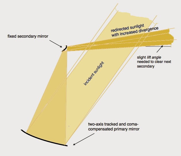
Redirecting light from a high sun toward a low target is implicitly an attempt to increase solar flux density—the Second Law of Thermodynamics requires either a compensating loss of energy (sunlight hits the ground) or an increase in beam divergence. An optical instrument that increases beam divergence while keeping the beam as collimated as possible (parallel rays are mapped to parallel rays) is called a telescope. Therefore, we must either resign ourselves to the wasteful land appetite of current CSP demonstrations, or begin investigation of telescopic heliostats and explore what their consequences will be for the rest of the system.

The difficulty in advancing a fundamentally new concept of CSP is that ultimate success depends on an ecology of new ideas and things, ideas and things that will never come into being unless a community of people endorse a common goal and individually see how their own possible contribution would fit. The same problem is faced by open source software projects, and a number of new tools and practices have fostered their successes. GitHub is a website for opensource software projects beginning to be used for open source hardware as well. The site provides a public and permanent record of incremental contributions—encouraging maximum openess from contributors—but also allows hive dispersal through forking, a facility that permits an independent-minded faction of contributors to take things in their own direction if their ideas do not find acceptance in the community as a whole.

Preliminary investigation of telescopic heliostats indicates that they improve mirror/land ratios from 0.21 to 0.70. Central, beam-down optics are unavoidable, but the necessary central optics, which look something like an overturned apple, need only 60% the height of a power tower on the same field. That makes larger heliostat fields practical.

Calculations indicate that a solar generating unit harvesting a quarter-township, a Public Land Survey System unit which is nine square miles (23,000,000 m2,) would need central optics 190 m high—that is just 15% taller than the current generation of power towers (the Crescent Dunes tower is 165 m.) Based on the performance of Ivanpah Unit 1, which is rated 126 MW at 32% capacity factor, with no storage, and harvests a land area of 3,800,000 square meters, the increased field area, and the improved mirror/land ratio (0.70 vs. 0.21,) a quarter-township solar generating unit in the Desert Southwest should be rated about 1 GW at 75% exploiting a half-day of thermal storage.

126 MW * (0.32/0.75) * (0.70/0.21) * (23,000,000 m2 / 3,800,000 m2)  = 1.08 GW

Ten things we know about telescopic heliostats

They're necessary. Ground loss—the quantity of sunlight falling between heliostats—is atrocious in current generation CSP's. Obvious in a satellite view is the fact that far more sunlight is reaching the ground than the mirrors. Land requirements are being tripled! The Second Law of Thermodynamics decrees that a heliostat without ground loss must act like a telescope, i.e., it must increase the divergence of the reflected beam while maintaining collimation (parallel rays map to parallel rays.)

Telescopic heliostats must have two mirrors. No fewer than two lenses (objective and eyepiece) compose a telescope.

Optimum power is about 6X. Magnifying the sun's disk, which is 0.5° in diameter, six times makes an intensified, but still collimated beam (or highbeam) that can be aimed at an elevation angle as small as its own diameter, 3.0°. That condition minimizes the height of the central, beam-down optics or lamp.

Central, beam-down optics are necessary. At 3.0° divergence, the highbeams are simply too spread to form a high quality focus without another optical stage.

The lamp (central beam-down optics)—shaped something like an overturned apple—will be only 60% as tall as a power tower on the same field. Larger heliostat fields are thus made practical.

The objective needs to move, the eyepiece doesn't. The objective (primary) mirror can redirect sunlight vertically to a fixed focus: the much smaller eyepiece (secondary) mirror gets to sit right there.

The objective needs to have its optical profile continuously fine-tuned to the sun's changing zenith distance. To first order, the adaptation needed is simply a thin-shell bending of the mirror.

Telescopic heliostats move in concert. The only real difference between two telescopic heliostats in a field is the azimuth aiming of their eyepieces. All the objectives could be mechanically ganged.

At at 0.70 mirror/land ratio, telescopic heliostats can be sited with negligible blocking. Surprisingly, the presence of the eyepieces adds no complication at all to heliostat siting when a phyllotaxis-based algorithm is used. The packing density achieved is more than three times that of a conventional heliostat field.

These improvements in field size and field packing make it practical to design a replicable 1 GW, 75% capacity-factor, standard solar plant covering one quarter-township (9 square miles) in the southwest U.S. The central lamp, about 190 m high, would be only 20% taller than current-generation power towers. Goodbye coal!


Monday, January 27, 2014

Quarter-township: the natural size of a replicable solar plant in the U.S.

The natural size of a replicable solar plant in the western United States is a quarter-township, or 9 square miles.

A solar power plant worthy of replication needs to be a good fit to its circumstances. In the western United States (Texas excepted) one part of those circumstances is the Public Land Survey System (PLSS,) a rectilinear grid to which property lines conform. Surveyed from reference points named for their meridians (e.g. San Bernardino Meridian, Gila and Salt River Meridian) the Public Land Survey System is a grid of six-mile by six-mile squares called townships.

In most of the American West, property lines conform to a national grid of 6 mi x 6 mi townships.
Another pre-existing circumstance for a solar thermal plant is the technology of steam-electric generating equipment. For many decades, electric utilities have preferred to build coal plants with multiple, separately-fired, turbine-generator units that are rated in the range of 600 MW to 1200 MW (see the chart below of the latest advanced high-temperature turbines installed by Siemens.)


Siemens' advanced steam turbines are commonly manufactured in the range of 600 to 1200 MW

New coal plants might operate at 80% capacity factor—i.e., their annual output is equivalent to running full power for 80% of the time—a statistic dependent not only on equipment reliability, but also on steady demand for electricity at a price that exceeds fuel costs. Capacity factors tend to come down in competition with wind turbines and other sources that do not pay for fuel, but a utility would certainly expect a new generating plant, solar or not, to be running full power most of the time. The Gemasolar plant in Spain has demonstrated that a solar plant with thermal storage can achieve a 75% capacity factor.

Taking advantage of an excellent solar climate, California's Ivanpah Solar Electric Generating System Unit #1 achieves a capacity factor of 0.32 without any energy storage at all. It has a rated power of 126 MW from a land area of 3,800,000 square meters or 33 W/m2 of land area. The mirror-area/land ratio for this plant is only 0.21. Upgrading to telescopic heliostats would bring the mirror-area/land ratio to 0.70, boosting the rated power to 33 W/m2 * 0.70/0.21 = 110 W/m2 of land area.

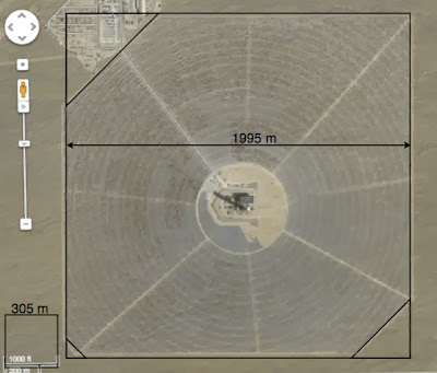
Based on Google imagery, the heliostat field of Ivanpah 1 is very nearly a square, 1995 m on a side, with three corner truncations, giving a heliostat field land area of about 3,800,000 square meters. This unit has 53,527 heliostats each with a mirror area of 15 square meters, giving a total mirror area of 803,000 square meters. The mirror/land ratio is 0.21.

Raising the 0.32 capacity factor of Ivanpah to 0.75 requires some amount of thermal storage (half-a-day, roughly) and a de-rating of the plant to 110 W/m2 * 0.32/0.75 = 47 W/m2 .

A quarter-township plant occupies a square of land 3 miles (4,828 m) on a side, having a land area of 9 square miles or 23,000,000 m2. Therefore, in Ivanpah's excellent solar climate, a quarter-township solar highbeams plant would be rated about 47 W/m2 * 23,000,000 m2 = 1.1 GW at a capacity factor of 75%.

Of course, the precise rating of a quarter-township plant would depend on many details including the quality of the local solar resource, but the size constraint will be the same throughout the West: a quarter-township.

In round metric numbers, a quarter-township solar plant is 5 km x 5 km. The central optics will be about 190 m tall— not that much taller than the 160 m power tower at Crescent Dunes, Nevada, or the 169 m (all-masonry) Washington Monument.


Thursday, January 23, 2014

Transflection as a negative-one refractive index lens

Negative refractive index materials have not been found in nature so far, but the equivalent effect has been produced in artificially structured materials, or metamaterials. Substituting a negative refractive index into Snell's Law of Refraction shows that the angle of refraction also becomes negative: the refracted light will be bent back to the same side of the surface normal as the incident light. For solar power optics the case of a refractive index equal to negative one is of unique interest: such a lens can have an air-filled interior and exterior (the only structured material needed is at the interface) and the throughput is potentially 100% (at least the Second Law of Thermodynamics will not offended if it is.) Lens optics with negative-one refractive index (nori for short) is both a more precise and more concise description of what I have earlier described as transflection.

In talking about the divergence pattern of optical rays passing through a point, a useful homely analogy is to place the point in question at the center of a transparent earth: then incident rays can be specified by their geographic source, i.e., the geographic point they pass through on their way toward the earth's center; and the emergent rays can be described by their geographic sink, the geographic point they pass through on their way out. I further adopt an orientation of the globe such that the surface normal at the point of interest is a ray from the earth's center toward its north pole.

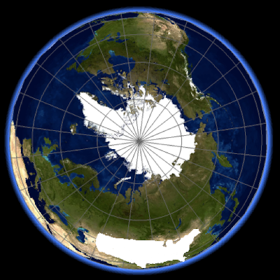
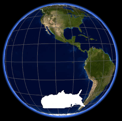
Using the analogy, we can describe the action of the four basic kinds of optical surfaces—window, mirror, retroreflector, and transflector—visually in terms of where they send rays sourced by a familiar geographic area, let's say the lower 48 American states.

Rays incident on a retroreflector completely reverse course and exit through the same geographic point they entered through:


Retroreflector

Rays incident on a window pass through undeflected, so each ray exits through the antipodes of its source (which, it turns out, is not Australia after all!)


Window

Rays reflecting from a mirror (having its surface normal pointing toward the north pole) will exit at the same latitude as their source, but 180° opposite in longitude.


Mirror


Mirror (with surface normal in center of view)

Rays exiting a transflector have the same longitude as their source, but their latitude is reflected to the opposite hemisphere.


Transflector
Note the similarity of the exit patterns for a transflector and a mirror when seen in the polar view (i.e., with the mirror normal in the center of the image.) For the mirror, the relationship between the incident and emergent ray distributions is a point reflection about the mirror's surface normal. This is equivalent to a 180° rotation about the point—left and right are not reversed. For the transflector, the emergent ray distribution is a reflection over a line (the equator)—and left and right are reversed. (Of course, in one sense, a mirror really does reverse left and right, but our way of describing ray directions is producing its own reversal as the plot for a window shows.)

Reflection about a point. (Image quoted from wikimedia.)


Reflection over a line. (Image quoted from http://geometry.freehomeworkmathhelp.com)


Reflection over a line can be equivalent to reflection about a point if the object has an axis of symmetry perpendicular to the line of reflection.


As diagrammed in the image above, if a divergence pattern has an axis of symmetry that perpendicularly intersects the mirror line, then we have a special case where reflection about the point of intersection is indistinguishable from reflection over the line. Therefore, given such a symmetry in the beam divergence, a Fresnel mirror with 90° facets can act as a nori lens. The radial symmetry of the heliostat field and the central optics about a common axis guarantees that the needed symmetry will exist.


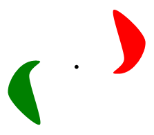
Beam divergence at the lamp (diagrammed in pink) will approximate a segment of a circle of latitude. In this view, the Fresnel mirror's surface normal will lie somewhere on the 0° line of longitude, fulfilling the constraint that it lie on an axis of symmetry for the divergence pattern. Therefore, for this divergence pattern, a Fresnel mirror with 90° facets can precisely simulate a nori lens.

 Gunnar Dolling and Martin Wegener, and R.Varalakshmi have demonstrated that POV-Ray correctly ray-traces in media with negative index of refraction.

Wednesday, January 22, 2014

Direct solar absorption and storage in high-purity glass melts

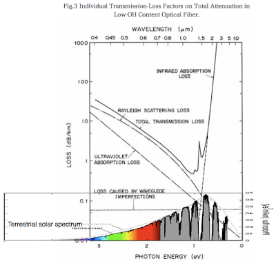
Terrestial solar spectrum superposed on the absorption spectrum of low-loss glass fibers.


At 1570 °C (a candidate "empty" temperature for a heat-storage glass melt,) the viscosity of soda-lime glass is only about half that of room-temperature honey; at 1800 °C (a candidate "full" temperature for a heat-storage glass melt,) its viscosity has fallen nearly to that of room-temperature motor oil. In a large storage pond of molten glass, convection will easily be turbulent; unfortunately, convection cannot be effectively driven by heating from the top.

Using the relations for the effective conductivity of soda-lime glass melts in Pilon et al. (which likely give values too low for high-purity melts because of the importance of the radiative contribution) the effective thermal conductivity of molten glass at 1570 °C is 95 W/m-°K (nearly twice that of room-temperature steel,) and it increases with temperature: at 1800 °C the effective thermal conductivity is 160 W/m-°K (comparable to room-temperature magnesium.) However, with a thermal diffusivity around 0.00004 m2/sec, a six-hour pulse of solar heating would only travel about 1 meter into the glass melt by conduction/radiation.

The only option for charging the thermal storage is a glass melt that is so transparent to solar radiation that much of the energy is absorbed in the lower half of the pond's depth. If half of the solar energy is absorbed in traveling to a 20 m depth, that is a loss rate of 3 dB/0.02 km = 150 dB/km. Data for very pure glass fibers (see diagram above) show that such transparency can be far exceeded for wavelengths shorter than 2 microns (which account for more than 90% of the AM 1.5 Direct solar spectrum, see diagram below.) It remains to be seen if such high-purity, transparent glass melts can be economical for direct solar absorption and storage.


Solar spectral distribution for AM 1.5 Direct (green line). Image quoted from http://pveducation.org .

Five advantages of the Solar Highbeams Project

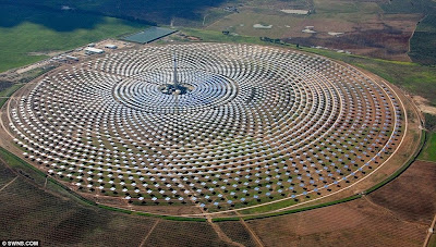
For the same central height, a solar highbeams plant harvests than three times the land area.  (Underlying image of  Ivanpah Solar Electric Generating System quoted from the Washington Post.)


A solar highbeams plant catches more than three times the sunlight from an acre of land. (Aerial photo of  Ivanpah Solar Electric Generating System quoted from Google Maps.)


Solar high beams heliostats all move identically; this allows them to be mechanically ganged.


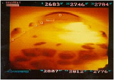
The focal zone in a solar highbeams plant is at ground level; this makes large-scale storage, power conversion, and industrial uses practical. (Glass furnace image quoted from Mirion Technologies.)


The rabbit advantage: because each solar highbeams power plant is a glass-making furnace as well, it can make the glass for additional plants. Making the glass for two more plants would delay power operations only a matter of months.

Tuesday, January 21, 2014

Truth in labeling: Solar multiple vs. capacity factor

It is natural to discuss a solar plant in terms of its rated output (i.e., peak electrical power,) but this often gives a false impression of the plant's economic value. For example, a utility might expect a new coal-fired plant to annually generate electric energy equivalent to its producing at full power 20 hours per day (capacity factor = 20/24 = 83%.) A solar plant in a desert climate will, over the course of a year, only produce energy equivalent to its producing at full power about 6 hours per day (capacity factor = 6/24 = 25%)

With energy storage a solar plant can operate with a higher capacity factor (saving money on some aspects of the plant) and making its rated output more directly comparable with a conventional plant. In a simplistic calculation, a 6 hr/day solar plant can become an 18 hr/day solar plant if we divert 2/3 of its output to storage. That is, by later withdrawing the stored energy we can have two more 6 hr periods of full power operation, giving a total of 18 hr/day. Our hypothetical solar plant would be said to have a capacity factor of 75%, 12 hours of storage, and a solar multiple of 3 (i.e., the ratio of its rated power without storage to its rated power with storage.)

In the real world, the above calculation would require a computer simulation, but we can borrow some real world numbers from Gemasolar, a thermal solar plant in Spain, which has 15 hours of storage and a 75% capacity factor. For obvious reasons, solar plants with a significant amount of storage prefer to advertise their annual electricity production rather than their rated power. From Gemasolar's stated annual production of 110,000 MWh/yr, and stated capacity factor of 75%, we can calculate that its rated power is:

110,000 MWhr/yr * (1/0.75) * (1/8760) yr/hr = 16.7 MW

Gemasolar has 304,750 m² of mirrors, so its rated power comes to 55 we/m² of mirror area.

Gemasolar and the Ivanpah thermal solar plant differ in detail (and Ivapah has the better solar climate,) but it is relevant to note that Ivanpah has three units rated 123 MW + 133 MW + 133 MW = 389 MW total, no storage, and 1,079,232 MWh/yr annual output—a capacity factor of 32%. In total, Ivanpah has 2,600,000 m² of mirror area, so its rated output of 389 MW comes to 150 We/m² of mirror area. That suggests that Gemasolar's solar multiple is about 150/55 = 2.7

The conclusion here is that solar plants without storage should be de-rated by approximately a factor of three before being directly compared with conventional fossil-fueled plants on the basis of rated power.


Thursday, January 16, 2014

Solar re-powering Georgia's Plant Bowen in sunny Spain

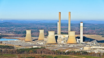
Solar re-powering Georgia Power's Plant Bowen to 3.2 GWe (75% capacity factor) in Andalucia's climate would require a storage/boiler compartment about 60% as tall as one of its cooling towers—and 130% its diameter. The central optics would be about 110% the height of its smokestacks.

In Andalucia, Spain, the location of the Gemasolar plant, only 15 hours of thermal storage (plus whatever solar multiple, or thermal down-rating, Gemasolar is using) is needed to achieve an annual capacity factor of 75% in a solar thermal generating plant.

Plant Bowen (3.2 GWe and 82% capacity factor) in Euharlee, GA, USA, is the largest coal-fired plant in the United States, and the country's largest point source of CO2 pollution. This post contemplates what Plant Bowen would look like if re-powered to run on the sun in Andalucia's sunny climate. Of course, it would be more interesting to see what Plant Bowen would look like solar-powered up to its own 82% capacity factor in northwest Georgia's own, somewhat less sunny, climate, but that would involve a detailed simulation. By figuratively moving Bowen to Spain, and adopting Gemasolar's 75% capacity factor, we can just steal data.

Quoting an earlier post:
Here are some statistics for Gemasolar gleaned from the National Renewable Energy Laboratory's site
Projected annual output: 110,000 MWhr/yr = 12.6 MWe  annual average.
Rated output  (calculated from the claimed 75% capacity factor): 16.7 MWe rated.
Output per mirror area (304,750 m2) :
       41 We/m2 annual average,
       55 We/m2 rated.
Land yield (1,950,000 m2; mirror/land ratio = 0.156):
        6.4 We/m2-land annual average,
        8.6 We/m2-land rated 
The 15 hours of storage based on 40% thermal efficiency is:
15 hrs * 3600 s/hr * 8.6 We/m2-land * 1/0.40 = 1.2 E6 Jthermal/m2-land 
A plant with telescopic heliostats and glass-melt storage would have some advantages over Gemasolar. Telescopic heliostats can be packed much more closely, increasing the mirror/land ratio to around 0.70, thus increasing land yield about 4.5 times that of Gemasolar. Also, because the glass melt transfers its heat to hotter steam (608°C vs. 565°C) the steam cycle efficiency can be greater, about 46% thermal efficiency as compared with 40%, a factor of 1.15 . 
So here are the Gemasolar statistics if it were rebuilt on the same plot of land with telescopic heliostats and glass-melt storage: 
Projected annual output: 110,000 MWhr/yr * 4.5 * 1.15 = 65 MWe  annual average.
Rated output  (calculated from the claimed 75% capacity factor): 87 MWe rated.
Output per mirror area (304,750 m2 * 4.5 = 1,370,000 m2) :
       41 We/m2 * 1.15 = 47 We/m2 annual average,
       55 We/m2 * 1.15 = 63 We/m2 rated. 
Land yield (1,950,000 m2; mirror/land ratio = 0.156):
        6.4 We/m2 * 4.5 * 1.15 = 33 We/m2-land annual average,
        8.6 We/m2 * 4.5 * 1.15 = 45 We/m2-land rated. 
The 15 hours of storage for the rebuilt plant becomes:
15 hrs * 3600 s/hr * 45 We/m2-land * 1/0.46 = 5.3 E6 Jthermal/m2-land 
Plant Bowen is a plant belonging to Georgia Power in Euharlee, Georgia. It is the largest coal-fired plant in the USA. It has four 800 MWe units, giving an aggregate rating of about 3.2 GWe. A telescopic heliostat / glass-melt power plant in Andalucia with 15 hours of thermal storage, having the same rated output of Plant Bowen, would occupy: 
3.2 GWe-rated / 45 We/m2-land rated = 71 E6 m2,
which is equivalent to a circle 4.8 km in radius.
The height of the central optics will be about 1/14 the field radius, or 340 m, or about 11% taller than Plant Bowen's 305 m smokestacks.
The heat flow to drive rated output is

3.2 GWe-rated * 1/0.46 = 7.0 GWthermal-rated

It remains to calculate storage and boiler dimensions. A boiler's water tube walls usually receive a thermal flux of around 250 kw/m2. Taking that value as a given, the total area of the water tube wall, SB, will be

SB = 7.0 GWthermal-rated / 250 kw/m2 = 28,000 m2.

The volumetric storage density in molten glass is

ΔT * 2300 kg/ m3 * 1231 J/kgK = ΔT * 2.8 E6 J/m3-K

Thermal storage needed for 15 hours of rated output is

7.0 GWthermal-rated * 15 hr * 3600 s/hr = 3.8 E14 J

So thermal storage volume V is

V = 1.35 E8/ΔT  m3

For a hemisphere

V = 2/3 π R3

so,

R =  (3/2π V)0.33 m

R = (3/2π * 1.35 E8/ΔT)0.33 m

R = (6.4 E7/ΔT)0.33 m

The height, H, of the water tube wall can be calculated from

2πR * H = SB


H = SB * 1/2πR = 28,000 m2 * 0.159 / R = 4,460/R m

Exploring these relations in a Numbers spreadsheet shows that Tempty = 1570 °C (1840 °K) gives a consistent solution with R = 63 m, H = 71, and the flux on the water wall tubes = 250 kw/m2. The glass temperature range from empty to full is just 230 °C. Tempty is approximately the temperature of a glass-making furnace, so it is fair to say that the thermal storage is accomplished by overheating a soda-lime glass-making furnace by about 230 °C.

By comparison, Plant Bowen has four cooling towers that are 47 m in radius and 116 m tall—so the volume of the storage/furnace compartment of a solar-fired Plant Bowen would be comparable in volume to one of its current cooling towers.

Radiative view factors in glass-melt solar storage


Radiative view factors between a cylinder and its endcaps. Diagram from Isidoro Martinez, "Radiative View Factors."

In radiative heat transfer, a view factor FA→B is the proportion of the radiation which leaves surface A and (directly) strikes surface B. In some cases there may also be an adiabatic blackbody surface C which, at thermal equilibrium, must re-radiate all of the photons it receives. In this case we can define an effective view factor  F*A→B that includes the re-radiated photons that reach B indirectly:

F*A→B = FA→B + (FA→C)(FC→B)

When all the surfaces are blackbodies (an assumption that greatly simplifies the math, and is approximately true in practice) the net radiative flux from A to B, averaged over  SA, the area of A, is:

ΦA = F*A→B * σ(TA4 - TB4),

where σ is the Stefan–Boltzmann constant, σ = 5.7 E−8 W m−2 K−4.

The corresponding net flux at surface B, ΦB, must be ΦA multiplied by the ratio of the two areas:

ΦB = ΦA * (SA/SB) = F*A→B * σ(TA4 - TB4) * (SA/SB).

When solar energy is stored in a glass melt, we can consider the free surface of the melt to be surface A (the lower cap of a cylinder,) the water wall tubes of the boiler to be surface B (the walls of the cylinder,) and the roof of the furnace to be the adiabatic surface C (the upper cap of the cylinder.)

Water wall tubes. Image quoted from http://tubeweld.com.
In the view factor diagram above, a reduced radius 'r' is related to the cylinder's radius, R, and its height, H, by:

r = R/H,

and a parameter ρ is defined to be:

ρ = (√(4 * r2 + 1) -1) / r.

The correspondences between our lettered surfaces and the diagram's numbered surfaces are:

A = 3, B = 1, C = 4.

From the diagram,

FA→B = F3→1 = ρ/2r

FA→C = F3→4 = 1 - ρ/2r

FC→B = F4→1 = F3→1 = ρ/2r

So,

F*A→B = FA→B + (FA→C)(FC→B) =  ρ/2r + (1 - ρ/2r)(ρ/2r) = (ρ/2r) (2 - ρ/2r),

and the area ratio, SA/SB, is

SA/SB = πR2 / 2πRH = R/2H = r/2.

The average flux on the water wall, ΦB, is

ΦB = F*A→B * σ(TA4 - TB4) * (SA/SB) = (ρ/2r) (2 - ρ/2r) (r/2) * σ(TA4 - TB4)

ΦB = (ρ/4) (2 - ρ/2r) * σ(TA4 - TB4)

With R = 51 m, H = 87 m, r = 0.58, ρ = 0.93, TA = 1610 °K (1340 °C) , TB = 730 °K (460 °C), as calculated in an earlier post,

ΦB = (ρ/4) (2 - ρ/2r) * σ(TA4 - TB4) = 0.26 * 367 kw/m2 = 96 kw / m2

which is not nearly the 250 kW/m2 we need to see on a water tube wall.

We need to increase radiant transfer by upping the "empty" temperature of the glass melt. This will also incidentally decrease storage density, resulting in an increase in R and a decrease in H (as calculated on the basis of 250 kW/m2.)


A spreadsheet exploring radiant transfer in glass-melt thermal storage.

Exploring these relations in a Numbers spreadsheet shows that Tempty = 1570 °C gives a consistent solution with R = 63 m, H = 71, and the flux on the water wall tubes = 250 kw/m2. The glass temperature range from empty to full is just 230 °C.

Wednesday, January 15, 2014

How wind kills coal

How wind kills coal. Underlying graphics from a report by the NREL.

Imagine you are a coal plant (gray area) that needs to run continuously to earn the ROI the investors were promised. Yikes, indeed!

Today Germany, tomorrow the world.

Tuesday, January 14, 2014

Maximum temperatures in glass-melt solar storage

Temperature field in a glass-making furnace in °K. (1820 °K = 1550 °C.)  Image quoted from L. Pilon et al.

As calculated in a previous post, the minimum (i.e., empty) temperature of a glass-melt storage is about 1340 °C (1610 °K) because of the need to supply high radiant flux (about 250 suns) to the steam tubes in order to achieve rated output. The maximum temperature depends on the high temperature materials available for the tank, the furnace roof, and the shading elements that modulate the radiant flux on the stem tubes.


Properties of ultra-high-temperature ceramic insulation. Image quoted from Rath USA.

Being optimistic, I'll say 1800 °C is an acceptable maximum glass-melt temperature—that's 250 °C hotter than a glass making furnace.

The storage temperature range is 1800 °C - 1340 °C = 460 °K, and the mean temperature is 1470 °C.  From Pilon et al., the specific heat, c, of molten glass between 1000 °C and 2000 °C is about 1231 J/kgK, so a 460 °K storage range stores 460 * 1231 = 566,000 J/kg. The density of molten glass in this temperature range is about 2300 kg/m3, so the volumetric energy storage is 1.3 E9 Jthermal/m3.

From the previous post, we need 5.3 E6 Jthermal/m2-land to store 15 hours of heat for rated output, so, spread over the land area of the heliostat field, the storage glass would form a layer 5.3 E6 / 1.3 E9 = 4 mm thick. That is less glass than would be needed for the mirrors!

Again from the previous post, the total land area for 3.2 GWe Gemasolar plant is 71 E6 m2, so the total storage volume is 71 E 6 * .004 = 284,000 m3, equivalent to a hemisphere with radius, r:

pi * 2/3 * r^3 = 284,000

r = 51 m, a pool with a perimeter of 2*pi*r = 320 m

At a thermal efficiency of 0.46, the rated thermal power is 3.2 E9 / 0.46 = 7.0 E9 Wthermal.

At 250 suns, the furnace wall area is 7.0 E9 / 250,000 = 28,000 m2.

With furnace wall area arrayed around the 320 m perimeter of the pool, the furnace wall is 28,000 / 320 = 87 m high, that is close to the height of the actual furnace walls at Plant Bowen, which appear to be about 75 m tall in photos. But I think 87 m is too tall in relation to the pool diameter (102 m) to comport with the earlier assumption of a 0.7 view factor, so this calculation is going to need more iterations.


Capacity factor and hours of solar storage

The Gemasolar plant in Andalucia, Spain operates at an annual capacity factor of 75% using just 15 hours of thermal storage.

The 17 MWe Gemasolar power tower in Fuentes de Andalucía, Spain is designed to operate at an annual capacity factor of 75%, and has run continuously for as long as 36 consecutive days. This remarkable accomplishment is achieved with just 15 hours of thermal storage. Clearly 15 hours of thermal storage is about the right amount for a solar plant!

Here are some statistics for Gemasolar gleaned from the National Renewable Energy Laboratory's site.

Projected annual output: 110,000 MWhr/yr = 12.6 MWe  annual average.
Rated output  (calculated from the 75% capacity factor): 16.7 MWe rated. 
Output per mirror area (304,750 m2) :
       41 We/m2 annual average,
       55 We/m2 rated.  
Land yield (1,950,000 m2; mirror/land ratio = 0.156):
        6.4 We/m2-land annual average,
        8.6 We/m2-land rated

The 15 hours of storage based on 40% thermal efficiency is:

15 hrs * 3600 s/hr * 8.6 We/m2-land * 1/0.40 = 1.2 E6 Jthermal/m2-land

A plant with telescopic heliostats and glass-melt storage would have some advantages over Gemasolar. Telescopic heliostats can be packed much more closely, increasing the mirror/land ratio to around 0.70, increasing land yield about 4.5 times that of Gemasolar. Also, because the glass melt transfers its heat to hotter steam (608°C vs. 565°C) the steam cycle efficiency can be greater, about 46% thermal efficiency as compared with 40%, a factor of 1.15 .

Now, the same Gemasolar statistics if rebuilt on the same land with telescopic heliostats and glass-melt storage:

Projected annual output: 110,000 MWhr/yr  * 4.5 * 1.15 = 65 MWe  annual average.
Rated output  (calculated from the 75% capacity factor): 87 MWe rated. 
Output per mirror area (304,750 m2 * 4.5 = 1,370,000 m2) :
       41 We/m2 * 1.15 = 47 We/m2 annual average,
       55 We/m2 * 1.15 = 63 We/m2 rated. 
Land yield (1,950,000 m2; mirror/land ratio = 0.156):
        6.4 We/m2 * 4.5 * 1.15 = 33 We/m2-land annual average,
        8.6 We/m2 * 4.5 * 1.15 = 45 We/m2-land rated.
The 15 hours of storage for the rebuilt plant becomes:

15 hrs * 3600 s/hr * 45 We/m2-land * 1/0.46 = 5.3 E6 Jthermal/m2-land

Plant Bowen in Euharlee, Georgia, is the largest coal-fired plant in the USA. It has four 800 MWe units, giving an aggregate rating of about 3.2 GWe. A telescopic heliostat / glass-melt power plant in Andalucia with 15 hours of thermal storage, having the same rated output of Plant Bowen, would occupy:

3.2 GWe-rated / 45 We/m2-land rated = 71 E6 m2,

or a circle 4.8 km in radius. The height of the central optics will be about 1/14 the field radius, or 340 m. This is about 11% higher than Plant Bowen's two 305 m smokestacks.

Plant Bowen, 3.2 GWe,

Friday, January 10, 2014

Direct absorption and storage of solar energy in glass melts

In a glass-making solar furnace, solar energy is directly absorbed in the semi-transparent melt.

Contrary to popular belief, renewable power does not "need" energy storage. When a GW of wind or solar power is brought online, the electric utility's least fuel-efficient 1 GW of conventional generating capacity is forced into semi-retirement. That is, those particular generating plants no longer have a job when the wind is blowing or the sun is shining. Since we have about 4 TW of conventional generating capacity to semi-retire in this way, renewable power will not be hurting for energy storage anytime soon. 

That said, in a thermal power plant some energy storage comes free—or at least at no additional cost—in the form of thermal inertia. The larger the plant, the more running time is extended by thermal inertia—and the cheaper it is to deliberately increase. Any process served by a solar furnace may benefit from this inexpensive form of energy storage. Since an all-glass, glass-making solar furnace will be first and foremost occupied in making its own glass parts, it is reasonable to look at the thermal inertia in the glass melt itself. 

A 2002 paper by L. Pilon, G. Zhao, and R. Viskanta looked at the thermophysical properties of glass melts. A melt of soda-lime glass is substantially transparent to both sunlight and high-temperature thermal radiation, so molten glass effectively has high thermal conductivity when it absorbs solar radiation directly or cools radiatively from high temperatures. For example, at 1400 °C (1700 °K,) a soda-lime glass melt has an effective thermal conductivity (phonic conduction + radiation) of 58 W/m-°K—that's more than the thermal conductivity of steel at room temperature.

Pilon et al. also give some representative numbers for industrial glass-making. They considered a glass melting tank approximately 16 m long, 7 m wide, and 1 m deep heated from above with a total heat input of 8.3 MW which averages to 72 suns (i.e., kw/m2) over the free surface of the melt. They estimate a maximum heat flux of 134 suns near the center. At melt surface temperatures around 1500 °C (1800 °K) they associate the maximum flux with vertical temperature gradients of about 1200 °C/m. At about 8 MWth, such an industrial glass-making furnace is only a small-scale model of a GW-scale solar glass-making furnace.

A coal-fired furnace for a 800 MWe generating unit might be 20 m x 20 m x 100 m high, corresponding to an average thermal flux per unit wall area of about 250 suns.

T-s diagram for a supercritical power plant. According to L & T Power, typical temperatures at points E and G for current technology are 565°C and 593°C, respectively; efficiency = 42%.


Heat balance for an advanced 800 MW power plant. Image quoted from Song Wu et al., "Technology options for clean coal power generation with CO2 capture." Mean temperature in the first heat (596 + 293)/2 = 445°C; second heat (608 + 342)/2 = 475°C; efficiency = 46%.

The steam tubes absorb heat over a range of temperatures, but 460°C may be taken as representative for the advanced supercritical cycle in the diagram above. At 460°C, a blackbody radiator emits about 16 suns (20 kw/m2.) The molten glass will need to be significantly hotter at its "empty" temperature in order to transfer a flux 250 suns to the furnace's steam tubes (in order to drive operation at rated power.) If the product of the emissivities and the view factor is about 0.7, the glass melt must be at a temperature where a blackbody emits about 380 suns, that is, around 1340°C. Using the thermophysical properties of soda lime glass melts quoted in Pilon et al., and the modified Rayleigh number, Ra*, defined in Bolshov et al., 1340°C is well within the range of turbulent convection for soda-lime glass. If we assume the pool of molten glass is a hemisphere 100 m in diameter, and that the average volumetric heating rate is 30 kw/m3, we have Ra* = 3E13 when the glass melt is at 1340°C.


Thermophysical properties of molten glass as calculated from the relations in Pilon et al.

Convection flow patterns and isotherms in a hemispherical pool with isothermal walls and top. Image quoted from Bolshov et al. The modified Rayleigh number, Ra* = 1E8 above, and Ra* = 1E9 below—much lower than the Ra* = 3E13 estimated for a GW-scale energy store.
Observed turbulent convection at Ra = 6.8 E8. Image quoted from X. D. Shang, X. L. Qiu, P. Tong, and K.-Q. Xia, Phys. Rev. Lett. 90, 074501 (2003).

What does an adaptive primary do?


An adaptive primary is a concentrating mirror that redirects sunlight to a fixed focus—no matter where the sun appears in the sky. A mirror that accomplishes this task must adapt its curvature as the sun rises higher or sets lower in the sky. To a first approximation, the curvature of the mirror is toric, that is, the mirror is always approximately shaped like a small patch on the surface of a torus. The adaptation required is slight, the changes in curvature will be scarcely visible to a viewer looking sideways at the mirror.

In the animation above—rendered in POV-Ray using Mega POV—the zenith distance of the sun varies from 15°  to 75°, while the adaptive primary acquires a toric curvature by the thin-shell bending of an initially spherical mirror. The POV-Ray scene description file for the animation is here.

In addition to changing its curvature, an adaptive primary needs to follow the sun in two angular dimensions: turning to face the sun's azimuth while also tilting its normal to one half the sun's zenith distance. (At the most an adaptive primary only needs to be tilted 45° away from horizontal.)

Monday, January 6, 2014

How to upload a Processing animation to Vine

Vines may be the most efficient way ever invented to convey a technical idea, but getting animations you make in Processing up on Vine can be vexing. The procedure below has worked for me using a MacBook (OS X 7.0.4) and an iPhone (iOS 7.0.4.) In addition to Processing and Vine, the freeware and apps you will need are GraphicConverter for Mac, Dropbox for Mac and iPhone, and Vinyet for iPhone. To add sound you will need QuickTime 7 Pro.


In Processing, generate sequential 480 x 480 frame images numbering less than 144 (i.e., < 6 seconds @ 24 fps) using a zero-padded file numbering such as frame000.tif through frame139.tif.

GraphicConverter: File: Convert & Modify
Function : Convert
Destination format: MooV - QuickTime Movie
Options: Normal compression, 480 x 480, 24 fps
Select the range of .tif images to be used, and the destination folder for the .mov file.
Hit "Go."

Drag the resulting .mov file to your Dropbox folder.

Find the .mov file in the Dropbox app on your iPhone.
Click the up-arrow icon located on the bottom left of the screen.
Click "Save Video"—this saves the .mov file to your camera roll.

Open the Vinyet app.
Click on the photos icon at the bottom of the screen.
Click on the desired .mov file.
After your video displays, click on "Save" in the upper right.

Vinyet now wants to append more video, but the green bar at the top of the screen should show that you are just shy of Vine's six second limit: so click on the checkmark in the upper right.
Click on the curly V in the bottom right.
Add your Vine caption (noting the character count) and click "Dismiss" when you are done.
Select your Vine channel.
Click "Share Video."

After Vinyet declares your "successful"upload, you may want to verify on Vine that it really did upload successfully.

Note that you must have an email-associated Vine account for Vinyet to upload successfully to Vine.


To embed your darling new Vine post in a blog or web page:

Find your vine on the Vine app.
Click on the three gray dots in the lower right.
"Share this post."
"Embed."
Fill in the address for the link to be emailed to, and click "Send."
Find the email in your inbox; click on the link.
If you want just the bare, looping video to display, choose "Simple"; if you want the surrounding info that you normally see on Vine, choose "Postcard."
Choose pixel dimensions. Note that 600px is more resolution that you uploaded. 320px transfers fast.
If there is an audio channel in your video, choose whether you want it to start playing automatically, or only at the viewer's request.
Copy the link displayed and paste it into the html of your blog post.
Surround the link with <center> …</center> if you want your vine to display centered in the column of text.


If you want to add a soundtrack to your Processing-generated vine (without using iMovie,) this can be done with Quicktime 7 Pro, which is an older version of the QT player that comes with the modern OSX. Quicktime 7 can still be downloaded directly from Apple, and, from my experience, it still accepts Pro registration numbers that may have been purchased many years back.

Create an audio track timed to exactly match the length your .mov file.
Export it as AIF 48kHZ 16-bit.
Open both the .mov and .aif files using QuickTime 7 Pro.
Select the aif sound file.
Edit > Select All.
Edit > Copy.
Now select the .mov video file. Make sure the playhead is at the start of the video file.
Edit > Add to Movie.
Select the video file.
Window > Show Movie Properties.
You should see your new soundtrack in the list of properties.
File > "Save as." Save it as a Self-Contained file. You must use "Save as," because "Save" fails to generate a new .mov containing the soundtrack.

QuickTime 7 Pro can also be used in place of GraphicConverter in the .mov making procedure above by using  File > Open Image Sequence, and then clicking on the first frame in the numbered sequence of frames; however, the exported .mov will be about 100 MB, which is much larger than necessary for 6 seconds of streamed video. Nonetheless, "Open Image Sequence" is a very handy tool for monitoring a work in progress. For example, render every 12th frame of your animation and then use "Open Image Sequence" at 2 frames per second with View > Loop checkmarked to see a quick rough draft of your vine.

Friday, January 3, 2014

Phi plus an integer (φ + n) heliostat arrangements


Since the center of the heliostat field will be occupied by the central optics anyway, it may be advantageous to arrange the heliostats in a higher frequency phyllotaxis spiral, i.e., φ + n dots per turn rather than φ dots per turn.

 The problem presented by a low frequency (for example, frequency = φ = 1.61803398… dots per turn) is that the genetic spiral—the spiral that connects each dot to the next in order of radial distance—becomes so tightly wrapped upon itself that it will be useless as a structural element or indexing principle. Since we don't need to pack primaries closely in the center field, we may be better off with higher frequency spiral.

Again, these packings still work if the the dots are radially oriented ellipses.


Such ellipses explore possible mutual blocking between secondaries. The video shows that secondaries of telescopic heliostats can be centered directly over primaries that arranged along a phyllotaxis spiral, and still reasonably fill the field of view from the central optics with little overlap (which would indicate one secondary blocking the beam of another.)

Processing sketch here.