Friday, February 28, 2014

Is beam-shaping necessary?

A Fresnel Veselago lens, without any beam-shaping, can produce an annular focal zone of modest concentration from a solar highbeams field.

Beam-shaping (reshaping divergence) at the Fresnel Veselago lens can potentially produce very high concentration at the oculus—and thus reduce thermal losses from the hot space—but this would come at a cost of complexity and reflection loss. Is this a marginal improvement we could postpone for later?

Since reflection losses in beam-shaping with lenticular lens arrays will probably subtract at least of 5% of the total power, and improving concentration at the oculus by a factor of four would reduce the radiant heat percentage, q, by the same factor, the improvement offered by beam-shaping is something like

0.75q - 0.05.

Assuming we would put off for now a 10% improvement in system power in the interest of simplification, that is, if:

0.75q - 0.05 < 0.1,

or q < 20% .

Radiant flux in the hot space at the 3/4-full temperature of 1936 °K is 800 suns (calculations included in the figure above too-generously assume radiant transfer at the empty temperature of 1250 °C = 1523 °K) this becomes a 20% loss when the incident flux is 4,000 suns. From the diagram above it looks like that is probably about four times more concentration than can be achieved at an annular focal zone without divergence reshaping. Adding a 2D CPC concentrator to the annulus or 2D radiation traps for thermal radiation escaping at wide angles might effectively double the concentration at the annulus to 2,000 suns, but that would still leave us a factor of two away, and we would really rather be at 8,000 suns so that heat loss is reduced to 10%.

A better approach is to bring light directly to a circular focal zone. Calculations in the diagram suggest we can get above 3500 suns without beam-shaping, and additionally we can  block much of the radiant heat loss by suspending an elliptical mirror over the oculus. (Sunlight is shown directly striking the boiler tubes, but this could be avoided by slanting the tubes, arranging them on the inside of a cone rather than a cylinder.)


A Fresnel Veselago lens, without any beam-shaping, can produce a circular focal zone with high concentration.

Is beam-shaping necessary? Likely not.

Wednesday, February 26, 2014

Improved model of thermal flux on the glass lake thermal storage unit

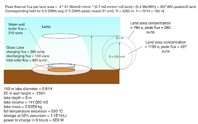
Thermal flux values at glass lake thermal store.
This design reduces the thermal flux at the boiler's water wall to 210 suns, the discharging flux at the lake surface is smaller than that because the lake has 1.5 times the area of the water wall. A much wider range of temperatures is used this time, 550 °C (1250 °C - 1800 °C) but the thermal stratification that occurs during charging allows only about 52% utilization of the glass lake's theoretical storage capacity. The depth of the glass lake and its optical absorption length are both 8 m. Two thirds of the peak solar power of 7.5 GWth goes to storage, giving a plant capacity factor of about 0.75.


Tuesday, February 25, 2014

Thermal flux at the glass lake

Thermal flux on a glass lake solar thermal store.

Assuming an average annual rated power of 51 We per m2 of mirror area, peak thermal flux will be about 4 x 51 x 0.71 / 0.4  = 357 Wth per m2 land area. Concentrating this flux on a circle having diameter equal to the optics height, H, would give a land-area concentration factor of 28 x 28 = 784, producing a thermal flux of 784 x 0.357 suns = 280 suns. To discharge the lake at 250 suns requires a charging flux of 500 suns, and, since one third of the incident flux is diverted to power generation, a total flux on the lake of 750 suns. That implies a lake with a diameter of 0.61H .

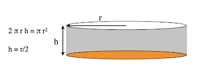
To have the same 250-sun flux at the water wall of the boiler and at the surface of the discharging lake requires the two areas to be equal, and thus the height of the water wall must be one-quarter the diameter of the lake (see diagram below.)


For the area of a cylinder's wall to equal the area of one of its end caps, the height of the wall must be one-quarter the cylinder's diameter.

For an approximately 1 GWe target design, with Rf = 2660 m, and H = 190 m, the lake diameter will be 0.61 x 190 m = 116 m, and the height of the boiler's water wall will be 116 m /4 = 29 m. To accommodate 2.5 times the thermal flux that was modeled in the previous post's thermal simulations requires a lake 2.5 times as deep, and, to keep the same maximum temperature, 2.52 = 6.25 times the optical absorption length. However, that would give a 25m-deep lake with a absorption length of 63 m—so something's got to give.

Charging and discharging transparent glass-melt solar thermal storage

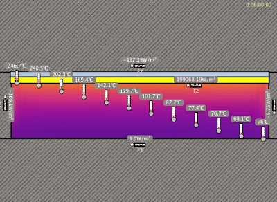
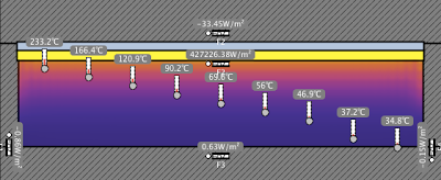
Molten glass thermal storage after 6 hours of solar charging from empty = 0.

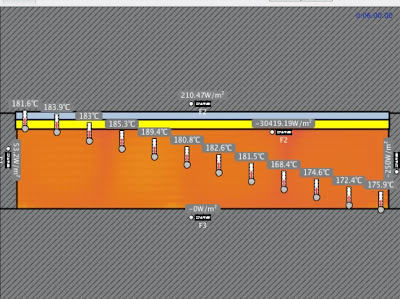
Molten glass thermal storage after 6 hours of radiant discharging from full = 250.
The two simulations above were run in Energy2D for a 10-meter depth of molten glass with a 10-meter optical absorption length, charging at 200,000 W/m2 and discharging at 100,000 W/m2. Charging produces a stable thermocline in the melt, while discharging drives natural convection that maintains a nearly uniform temperature within the convecting layer. Surprisingly perhaps, despite the high viscosity of molten glass, the natural convection during discharge is fully turbulent. The discharge simulation above had to be run at 1/10 earth gravity to keep convective turbulence at a scale the model could handle.


Friday, February 21, 2014

Direct solar absorption and storage in a molten glass thermocline

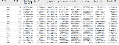
At high temperature, the effective thermal conductivity of molten glass becomes dominated by its transparency in the UV-to-2-micron passband. In the previous post it was calculated that molten glass at 2000 degrees K, with a 1/e (i.e., -4.3 dB) absorption length of 1 meter in the UV-to-2-micron passband (a loss rate of 4300 dB/km) would have an effective thermal conductivity of about 456 W/m-°K. The correlations for molten glass reported by Laurent Pilon et al., summarized in this chart, indicate an effective thermal conductivity of molten soda-lime glass at 2000 °K of 137 W/m-°K. From that value it can be estimated that the 1/e absorption length of soda-lime glass of commercial purity is about 137/456 m = 0.3 m. That is a figure that comports with everyday experience (e.g., looking through a glass panel edgewise.)


Thermophysical properties of molten glass at high temperature, including effective thermal conductivity, calculated from correlations in Laurent Pilon et al.


Absorption in the UV-to-2-micron passband of glass is almost entirely due to metal ion impurities, mainly iron. Thus improving the purity of ordinary glass by a factor of ten would extend the absorption length to 3 meters and increase effective thermal conductivity to about 1400 W/m-°K—about three times the room-temperature thermal conductivity of silver.

High effective conductivity also suppresses natural convection since natural convection starts out as a wiggle in an isotherm that enlarges by gravitational instability—despite viscosity slowing it down—faster than it can be damped out by thermal diffusion.

Solar radiation is 90% within the UV-to-2-micron passband of glass, so it plays by the same rules as the conductivity-dominating thermal radiation. A net flux of say, 0.4 MW/m2, onto the top of the glass melt will not penetrate any more deeply if it is the result of solar radiation or thermal radiation (aka, effective conduction.) Sunlight has relatively more short wavelength energy, of course, but under the assumption of spectrally uniform absorption in the UV-to-2-micron band, this makes no difference.

Flux is flux. That greatly simplifies modeling.


Solar heating of a glass melt from above stores heat in a stable thermocline. Later radiant cooling of the melt from above "excavates" the stable thermocline removing heat by natural convection from successively deeper and deeper levels until the whole melt is at the "empty" temperature. Temperatures in the diagram are measured relative to empty. Modeled in Energy2D.  Depth 10 m, absorption length 10 m, shown after 6 hours of solar heating.

Thursday, February 13, 2014

Effective thermal conductivity of high-purity glass melts

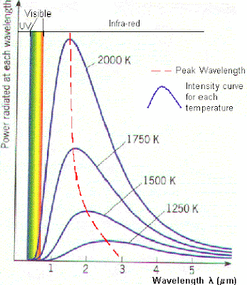
The effective conductivity of high-purity glass melts increases rapidly with temperature because the melt is semi-transparent to its own thermal radiation. At wavelengths shorter than 2 microns a high purity glass melt may permit its own thermal photons to travel some meters, in some cases even tens of meters, before being re-absorbed. At temperatures used for solar thermal storage, 1840 °K to 2070 °K, about a quarter to a third of blackbody radiation is in the below-2-micron passband of glass. Since effective thermal conductivity is proportional to the average distance a blackbody photon travels before it is reabsorbed, the effective conductivity of a glass melt is a function of its level of purity.


At absolute temperature T, blackbody radiation is

σT4,

where σ is the Stefan-Boltzmann constant,

σ = 5.7 E−8 W m−2 K−4 .

The derivative of blackbody flux with respect to T is:

 4σT3 W/m2-°K,

 which is the transfer between two blackbody surfaces differing slightly in temperature. At glass-melt storage temperatures only about a quarter of the blackbody radiation is in the below-2-micron passband of the melt, so we are only concerned with a differential flux of about

σT3 W/m2-°K.

If the average temperature is 2000 °K and photons in the passband travel a distance of one meter, the effective thermal conductivity (ignoring actual phonic conduction which will be relatively small) is

(5.7 E−8 W m−2 K−4)(2000 °K)3(1 m) = 456 W/m-°K

Compare the thermal conductivity of silver at room temperature is 429 W/m-°K.


Wednesday, February 12, 2014

High-purity glass melts for solar thermal storage: how pure? what cost?

High-temperature, thermal buffer storage increases the capacity factor of a solar electric plant and thus reduces the cost of thermo-mechanical conversion and electricity generation and transmission. As power sources like wind and photovoltaic—which lack access to inexpensive energy storage—become more common in the utility mix, an increasing value of high-temperature thermal storage will be permitting  time-shifting daily output to seek better electricity prices. Another value of buffer storage, which may or may not be minor, is reducing the thermal cycling of the expensive high-temperature conversion equipment. Here, I will only attempt to assess the first value, the value due to increased capacity factor

Dirk Pauschert in "Study of Equipment Prices in the Power Sector" estimates the cost of an 800 MW supercritical coal-fired power plant at $1960/kw (2008 US$). While that includes costs specifically associated with coal combustion, it also does not include the significant transmission costs associated with a remotely sited solar plant—so I will not apply a correction, $1960/kw it is.

I assume adding 20 hours of storage allows a solar plant to improve its capacity factor from 0.25 to 0.75 (without significant increased losses.) Thus a plant that would have needed 1 kw of turbine/generator capacity with no storage, only needs 0.33 kw of turbine/generator capacity with 20 hours of storage (i.e., having a capacity factor of 0.75 instead of 0.25, it has three times as long to generate the same kilowatt-hours.) That saves two-thirds of the original $1960 cost of the plant, a savings of $1313. With a heat-to-electricity conversion efficiency of 0.40, the thermal storage needed achieve that savings is:

 (20 hours) * (0.33 kwe) / (0.40) = 16.5 kw-hrth

Given that two other sources of value were ignored, a conservative estimate for the value of thermal storage is:

($1313) / 16.5 kw-hrth  =  $80 / kw-hrth.

Quoting an earlier post about thermal storage in high-purity glass melts:
From Pilon et al., the specific heat, c, of molten glass between 1000 °C and 2000 °C is about 1231 J/kgK...
Another previous post found that the practical delta-T for molten glass storage (bounded by a practical maximum temperature for the insulated roof of the furnace and the need for intense radiative transfer to the boiler tubes) is 230 °C. So a 230 °K storage range stores 230 * 1231 = 283,000 J/kg.

Converting that storage density to kw-hrth/t:

(283,000 Jth/kg) * (1000 kg/t) * (2.8 E-7 kw-hrth/Jth) = 79 kw-hrth/t

Thus the economic value of one ton of high-purity glass employed in this way is:

($80 / kw-hrth) * (79 kw-hrth/t) = $6,340 / t

This seemingly high value per ton is not out of line with more familiar high-temperature options.


Table comparing cost and performance of high-temperature thermal storage materials. Image quoted from Xiangyu Meng et al., "Theorectical Investigation of solar energy high temperature heat storage technology based on metal hydrides."


For example, the table above quotes nitrate salts as costing $1700/t, and states that they store 77 kw-hrth / m3, or 41 kw-hrth/t —about half as much thermal storage per ton—and at lower temperature than molten glass (which signifies lower conversion efficiency.)

To quote Reiner Haus et al. in "Assessment of high purity quartz resources,"

Beneficiation of raw quartz into refined high-purity products involves several refinement steps which need to be adapted to effectively minimise the specific impurities of the individual raw quartz feed to comply with stringent end-use specifications (Haus 2005). As a result, high purity quartz with total impurity levels less than 20 ppm may be achieved so creating a highly valuable raw material which commands up to 5 EUR/kg.

That is, 20 ppm high-purity silica is currently available at $7,000 / t.


Optical attenuation in glass-melt solar storage is somewhat similar to attenuation in optical fibers, about which much is known. The spectral attenuation graph for silica fiber reproduced below, shows that, barring metallic ion impurities, there are two different sources of attenuation. At short wavelengths the attenuation is mostly due to Rayleigh scattering; at infrared wavelengths, most of the attenuation is due to OH impurities, and eventually, in the longer infrared, attenuation is due to the tail of the absorption Si-O bonds of the silica itself.


Rayleigh scattering and OH absorption in silica optical fibers. Image quoted from Giusy Origlio, "Properties and Radiation Response of Optical Fibers: Role of Dopants." 
In glass-melt  thermal storage we need much of the solar energy to penetrate deep into the melt to stir its lower half. We do not need particular wavelengths reach the depths. The figure below shows that about half of the energy in solar radiation is shorter than 0.75 microns—and thus more than half of solar energy lies in the region where attenuation is mainly due to Rayleigh scattering.
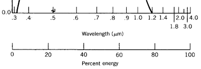
Percentage of solar radiation shorter than a given wavelength. A wavelength distorted scale quoted from www.powerfromthesun.net .

That is good news because Rayleigh scattering, which is due to thermal inhomogeneities in the glass matrix itself, depends on temperature not on purity. Thus the very difficult problem of reducing the "water peaks" caused by OH ions, which demands extreme purities in glass for optical fibers, does not arise in glass melt storage. For solar glass-melt thermal storage, the easier problem of reducing metallic ion impurities, Fe in particular, reigns instead.

Quoting the Wikipedia article on Rayleigh scattering:
Rayleigh scattering is an important component of the scattering of optical signals in optical fibers. Silica fibers are disordered materials, thus their density varies on a microscopic scale. The density fluctuations give rise to energy loss due to the scattered light, with the following coefficient:[7]

\alpha _{{\text{scat}}}={\frac  {8\pi ^{3}}{3\lambda ^{4}}}n^{8}p^{2}kT_{{\text{f}}}\beta

where n is the refraction index, p is the photoelastic coefficient of the glass, k is the Boltzmann constant, and β is the isothermal compressibility. Tf is a fictive temperature, representing the temperature at which the density fluctuations are "frozen" in the material. 
Fictive temperatures for silica glass range from 1373 °K to 1773 °K (1100 °C to 1500 °C); by comparison the temperature range in a glass-melt storage is  1840 °K to 2070 °K (1570 °C to 1800 °C). Since the dependence of scattering on absolute temperature is only linear, there should be about a 25% increase in Rayleigh scattering in a thermal storage glass-melt as compared to an optical fiber.

Since we are now utilizing only half the of solar spectrum to heat the bottom of the melt, short-wavelength attenuation in the melt can only be about 75 db/km, in other words, we need about half of the short wavelength solar energy needs to reach the very bottom of the glass melt. As the figure below shows, Rayleigh scattering only rises that level in the ultraviolet.

Spectral attenuation of glass fiber materials showing short-wavelength Rayleigh scattering for silica. Quoted from Giusy Origlio, "Properties and Radiation Response of Optical Fibers: Role of Dopants." 


Attenuation due to metallic ion impurities in optical fibers. Quoted from Murata, "Handbook of Optical Fibers and Cables."
The chart above suggests that a concentration of about 60 ppb of Fe2+ could be tolerated in a glass-melt used for solar energy storage. That level of purity, 60 ppb, is still about 300 times the purity of the 20 ppm silica that is currently available at a price affordable for use as thermal storage.

Absorption by iron depends on the oxidation state of the ion, the ferrous, Fe2+, or the ferric, Fe3+. It appears that the more oxidized state, Fe3+, might be preferable for solar energy storage, because of lower absorption. Quoting from Bahman Mirhadi and Behzad Mehdikhani,"Effect of Batch Melting Temperature and Raw Material on Iron Redox State in Sodium Silicate Glasses":

Because iron has two redox states, Fe2+ and Fe3+, and these states have different colors, control of the redox condition during melting is important in adjusting the transmittance of glass in the wavelength regions of UV, visible light, and IR. When melted glass is placed in a reductive environment, the content of Fe2+ increases, and the glass turns bluish green because Fe2+ has a broad absorption band centered at 1050 nm. This absorption band is utilized in IR-cut glass such as cold-filtered glass which is produced under reductive conditions. When melted glass is placed in an oxidative environment, the iron in the glass is oxidized to the Fe3+ state and produces a yellowish color due to an absorption band which shows strong absorption below 380 nm that tails off towards longer wavelengths up to about 450 nm.
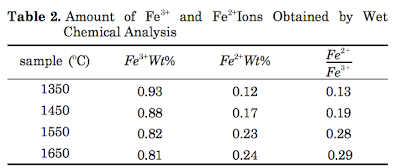

Mirhadi and Mehdikhani found that the redox ratio, Fe+2/Fe3+, increases in the solidified glass with melt temperature, reaching a plateau at about 0.3. 


Mirhadi and Mehdikhani found that the redox ratio, Fe+2/Fe3+, increases in the solidified glass with melt temperature, reaching a plateau at about 0.3. If Fe3+ is indeed strongly preferable, then 180 ppb of total iron may be acceptable in a glass melt used for solar energy storage since only a third will be in the  more absorbing Fe2+ redox state. That is still 100 times the purity of silica currently available at an acceptable price.

Tuesday, February 11, 2014

Visualizing telescopic heliostat beaming angles

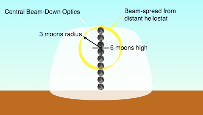
Beaming angle and beam diameter visualized in comparison with the angular diameter of the full moon.
The nominal condition for a telescopic heliostat is 6x linear magnification (producing a beam diameter of six solar or lunar diameters—they are nearly the same) beamed at an angular elevation of 3° (also equal to six lunar or solar diameters.)

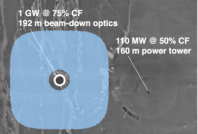
Solar Highbeams Target Design compared with Crescent Dunes

The Solar Highbeams Target Design compared with the Crescent Dunes Solar Energy Project. Underlying image quoted from Google Maps.


Table comparing the Solar Highbeams Target Design with the Crescent Dunes Solar Energy Project.
The ratings assume that the annual average power per mirror area of Crescent Dunes (51 W/m2) can also be achieved in the target design. Maximum boiler temperature at Crescent Dunes is 565 °C (1050 °F).

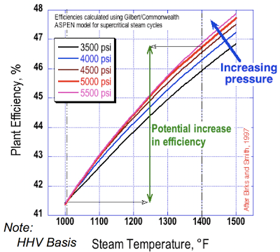
Advanced steam turbine technology: plant efficiency vs. steam temperature. Image quoted from EPRI, "Materials Technology to Enable High-Efficiency Advanced Ultrasupercritical (A-USC) Steam Power Plants"

The plot of plant efficiency vs. steam temperature above suggests that increasing steam temperature from Crescent Dunes' 565 °C (1050 °F) to an A-USC (advanced ultra supercritical) turbine's 760 °C (1400 °F), would increase plant output by about a factor of 46.5/42.3 = 1.10. That gives some leeway in rating the Solar Highbeams Target Design at 1 GW though its atmospheric turbidity losses will be greater than Crescent Dunes', and possibly its rather different shading and blocking losses will be greater as well. Eventually, thermophotovoltaic (TPV) conversion may offer even higher efficiencies.

Thursday, February 6, 2014

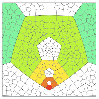
Self-replicant fractal growth patterns

Fractal growth of a pentagonal annulus. Underlying image from Bowers and Stephenson, "A 'regular' pentagonal tiling of the plane."


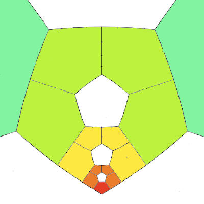
Same image as above with some of the un-needed boundaries erased.


Peripheral and non-simple fractal growth.

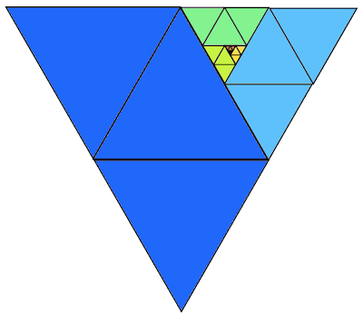
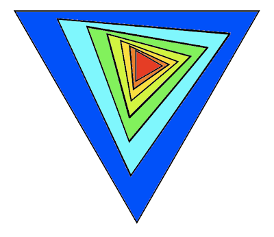
By self-replicant fractal growth I mean growth that incorporates at each molt or growth stage an increment that makes the shape a larger version of its earlier self. It is easier to think about fractal growth time-reversed as a repeated subdivision of a large tile into smaller tiles. The algorithm is simple: subdivide the large tile in a way that leaves a sub-tile that is geometrically similar to the large one; reapply the subdivision to the similar tile; repeat step two. (To completely specify the subdivision procedure it may be necessary to mark a point on the boundary of the large tile, and the corresponding point on the boundary of the similar tile.)

These patterns are either central or peripheral according to whether the intersection of the boundaries of the large tile and the similar tile is empty or not. The peripheral patterns can be simple or non-simple according to whether or not the boundaries intersection is connected. The pentagonal example above is peripheral and non-simple.


Peripheral simple fractal growth of a triangle.


Peripheral simple fractal growth of a triangle.


Peripheral non-simple fractal growth of a triangle.


Central fractal growth of a triangle.

Wednesday, February 5, 2014

The size range for all-glass, glass-making solar furnaces

LIMITS ON LARGE-SCALE, ALL-GLASS SOLAR FURNACES

At mega-scale, the height of the lamp when made of glass, is constrained by the specific strength of glass fibers, σ/ϱ, measured in Pa-kg/m3 = N-m/kg, which, when divided by the acceleration of Earth gravity, 9.81 N/kg, gives a characteristic breaking length. Using data for S-2 glass fibers , σ = 4.9 E9 Pa, ϱ = 2460 kg/m3, giving a breaking length of 200 km. This high value is only for pristine glass fibers, but the needed safety factor can be properly lumped-in with the yet unknown factor, very much less than 1, that, dependent on the lamp's structural design, converts the breaking length to the lamp height.

Another possible size-limiting factor is atmospheric turbidity. Mark Schmitz et al. in "Assessment of the potential improvement due to multiple apertures in central receiver systems with secondary concentrators," recommend an approximation for atmospheric attenuation, ηaa, between heliostat and receiver separated by distance dhr in meters:

ηaa = exp(-.00011 * dhr)

for dhr > 1000 m, and visibility = 40 km.

A quarter-township heliostat field (about 4.8 km x 4.8 km) has a maximum dhr of about (1.12) * (4,800/2) = 2,688 m, giving ηaa = 0.74; in other words, 26% of the redirected solar energy from the most distant heliostats would be lost to scattering on the way to the lantern. That would indicate quarter-township units are about the largest solar furnaces the turbidity of the atmosphere allows.


LIMITS ON SMALL-SCALE, GLASS-MAKING SOLAR FURNACES 

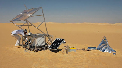
Markus Kayser with his SolarSinter glass-making solar furnace. Image quoted from www.creativeapplications.net .


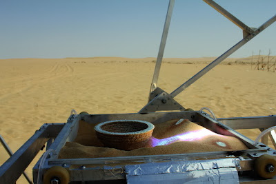
A glass bowl produced by SolarSinter.

The most down-scalable solar glass-making technique is Markus Kayser's SolarSinter, in which sunlight is directly focussed onto sand. The thermal conductivity, κ, of sand, about 0.2 W/m-°K, limits how steep a thermal gradient can be created using a given thermal flux. The optical flux achievable in a solar furnace is the flux seen on the sun's surface as attenuated by Earth's atmosphere—about 40 E6 W/m2—multiplied by the square of the non-dimensional numerical aperture (NA) of the optics.

Microscope objectives of different NA. Image quoted from www.microscopyu.com
In air, numerical aperture can theoretically approach 1, but, more realistically, some headroom must be left between the optics and the melting sand. An NA of 0.87 (on the right of the image above), may be taken as a practical maximum. NA = 0.87 allows a solar furnace to achieve an optical flux of 40 E6 W/m2 * (0.87)2 = 30 E6  W/m2. The albedo of dry sand is about 0.4, so the actual thermal flux, Φ, is (1.0 - 0.4) * 30 E6 W/m2 = 18 E6 W/m2. A ΔT of approximately 2000 °K is needed to melt sand that is initially at room temperature. In one-dimensional, steady-state flow, 18 E6 W/m2 can produce a 2000 °K ΔT in a layer of sand of thickness δ,

 δ = κ ΔT / Φ = (0.2 W/m-°K) * (2000 °K) / (18 E6 W/m2) = 0.022 mm .
This is a best-case scenario since transient or 3-dimensional heat flow would require even greater thermal flux to melt the sand. Assuming we can reduce the radius of the focal spot, r, down to r = δ without stopping the sand from melting, then, working backward from the geometric concentration factor, C,

C = (30 E6 W/m2) / (1 E3 W/m2) = 30,000X ,

indicates that the solar furnace must have an entry aperture with radius R,

R = r √C = 170 * δ = 3.8 mm

For comparison, the radius of SolarSinter's Fresnel lens appears to be around 500 mm, so in theory it should be possible to down-size SolarSinter by something like two orders of magnitude.

However, the finite size of sand grains may set the actual bound. Fine sand grains may have diameter 0.125 mm to 0.25 mm  which is an order of magnitude larger than the value for δ calculated above. That suggests SolarSinter, when working with fine sand grains, can be down-sized just one order of magnitude to around r = 50 mm, or roughly a square 0.1 m on a side.

The size range from 0.1 m x 0.1 m to 6.25 m x 6.25 m is about 6 molts or linear doublings (areal quadruplings,) from there, there are nine molts (the last being extra large) to quarter-township size. Whether we start at 0.1 m x 0.1 m (requiring 15 molts) or 6.25 m x 6.25 (requiring 9 molts) growing a maximal-size terrestrial solar furnace takes something like three years.

Sizes of fractally-grown solar furnaces: a table of molts within the Synthetic PLSS.

Monday, February 3, 2014

Fractal growth of all-glass, glass-making solar furnaces

An all-glass glass-making solar furnace built through a sequence of five molts from a much smaller furnace.
Probably the fastest way to grow a solar furnace is to build three squares equal in area to the glass-making unit and then re-aim the heliostats of the glass-making unit (and dismantle its lamp) to constitute the fourth square. That way, the time, tm, to build the next molt is just 3x the glass replication time, tr, times an additional factor, i, accounting for the increase of glass thickness between molts. Generalizing from m = 4 to any molt area factor, m:

tm = (m - 1) * tr * i


Earlier it was assumed that the glass thickness would double in the course of a linear scale increase of 16, which corresponds to 4 stages (molts) of linear doubling. Therefore, in each molt, the glass thickness should increase by the fourth root of 2, or 1.189. The first molt requires 3 x 1.189 = 3.57 glass replication times to complete. For each later molt, the glass replication time increases by a factor of 1.189 on account of the increased glass thickness.

The fourth root of two is a rather small increase in glass thickness for a doubling in linear scale, but the value is based on the fact that heliostat size does not need to increase in proportion to field size. At larger scales, the lamp—being all of one piece and not scaled to the heliostats—becomes a larger portion of the total mass, so the glass thickness factor must increase somewhat. Also, when going down to much smaller scales the thickness factor must in the limit approach 2 (the factor for geometric similarity) to prevent mechanical interferences. Another way to think of it is that the field cannot be composed of fewer than one heliostat.

Starting with a small molt 0 unit having replication time tr, m = 4, and molt thickness multiplier i, growing to molt n requires build time, tb:

tb = tr * 3 * i * (1 + i + i2 + i3 … + in-1)

tb = tr * 3 * (i + i2 + i3 … + in)

For i = 1.189, the ratio tb / tr  to reach successive generations is

1     3.6
2     7.8
3   12.9
4   18.9
5   26.0
6   34.5
7   44.5
8   56.5

For example, growing a molt 0 unit that is 6.25 m square up to a unit 1600 m square requires 8 molts. If the glass replication time of the molt 0 unit is ten days, growing from that unit to a unit approximately one mile square takes 565 days, or a bit more than a year and a half.

The final molt will probably use a molt area factor, m, larger than 4, because it makes little sense to gather the forces to build a large project in a matter of a few months unless they can move directly on to something else. Using a final molt area factor, mf, of 9 in the last stage effectively becomes 1.59 molts since

mf = 9 = 41.59 .

The time, tmf , required for the final molt is

tmf = (mf - 1) * (tr * in) * ln(mf / m)

where tr is the glass replication time for molt 0, i is the glass thickness factor for the earlier molts, n is the number of the next-to-final molt, and m is the molt area factor for the earlier molts.

Here,  m = 4, mf = 9,

tmf = 8 * (tr * in) * 1.59 = 12.7 * (tr * in)

For the growth sequence of eight molts mentioned above, n = 8, and the final molt with mf = 9 has

tmf / t= 12.7 * i8

For i = 1.189,

tmf / t= 12.7 * (1.189)8 = 50.7

The total 9-molt build from a 6.25 m square to a quarter-township takes (56.5 + 50.7) * t = 107 * t.

If the glass replication time for the 6.25 m x 6.25 m solar furnace is ten days, it can grow to occupy a quarter-township in 1070 days, a little less than three years.

Starting from a smaller scale would only add a few days to the total. In fact, in the range where i = 2, the time for each molt is the sum of the times for all previous molts. In the case considered that would mean that all molts preceding our molt 0 would total less than 10 days, no matter how small we start.

Therefore, a quarter-township all-glass, glass-making solar furnace can be grown in a matter of a few years no matter how small the seed. 

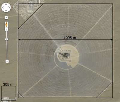
Ivanpah Unit 1 specifications on a square-field basis

Ivanpah Unit 1 sits on a 1995 m x 1995 m square of land.
The previous post makes me think it is necessary to pro-rate the specifications of CSP power tower's over the area of the square of land they take out of use. Here are the specifications of Ivanpah Unit 1 on that basis.

Peak Rating of Units 1 + 2 + 3 = 392 MW

Electricity Generation Expected from Units 1 + 2 + 3 = 1,079,232 MWh/yr

Overall Capacity Factor for Units 1 + 2 + 3 = 0.314

Peak Rating of Unit 1 = 126 MW

Area of Unit 1's Square Field = 3,980,000 m2

Peak Rating of Unit 1 per unit of square field area = 31.7 W/m2

Levelized (100% capacity factor) rating of Unit 1 per unit of square field area = 0.314 * 31.7 w/m2 = 9.96 W/m2

U.S. per capita electricity consumption is 1400 W/person (at 100% capacity factor)

Per capita land claim for electricity (per Ivanpah Unit 1) would be 1400/9.96 = 141 m2 per person

According to page 1-3 of the environmental impact statement, the power tower is 140 m tall, and Unit 1 has 55,000 heliostats, each having 14.08 m2 of reflective surface.

Mirror area of Unit 1 = 14.08 m2 * 55,000 = 774,400 m2

mirror-area / square-field-area = 0.195


Telescopic heliostat fields are expected to produce 3 times the land yield of conventional heliostats, thereby reducing the land claim to 47 m2/person, increasing levelized (100% capacity factor) rating to 30 W/m2, and giving a 75% capacity factor (representative of a plant with half-day thermal storage) rating of 40 W/m2—all on the basis of square-field area.

75% capacity factor rating for a 1600 m x 1600 m unit would be 102 MW, or 920 MW on a quarter-township.

For these numbers to hold up, the mirror-area/square-field-area of a telescopic heliostat field must be better than 3 x 0.195 = 0.585

Starting from a covering factor of 0.91, and losing another 0.02 of covering factor around the lamp means that achieving 0.585 overall requires an intrinsic fill of 0.585/(0.91-0.02) = 0.66.


Fitting a circular heliostat field in a square plot

Diagram of an oversized, circular heliostat field in a square plot of land.

A heliostat field wants to be circular, but plots of land are square.  Determining how much of a square plot to cover with heliostats would require a complex optimization, and it seems unlikely that filling the square all the way out to its corners would be the result.

An initial, plausible solution is an oversized circle with energy loss (land in the corners not covered by heliostats) that is twice as big as brightness loss (portions of the oversized circle that will be truncated by the square.) The reason to prefer energy loss, is that it is cheaper: we've already paid for the lamp to handle the radiation that brightness loss causes to go missing. By comparison, un-built-upon land is cheap.

By symmetry, this problem can be solved by looking at a single octant of the square and circle. From the diagram, the area of the full square exceeds the area of the full circle by 8*A. Assuming the circle is a unit circle, area A is:

A = (π*θ/2π)  - (sinθ cosθ)/2

= θ/2 - (sinθ cosθ)/2

Since the square, having side length s, exceeds the area of the circle by 8*A,

π + 8*A = s2,

π + 4θ - 4sinθ cosθ = s2.

Also, s = 2cosθ, so

π + 4θ - 4sinθ cosθ = 4cos2θ

which is solved by

θ ≈ 0.421 radians, or 24.1° .

The circle diameter, d, is s/cosθ = 1.096 s .


Nine heliostat fields on square plots with d/s = 1.096.


Getting a handle on the value of land is difficult because its value changes when we build on it; also, once a property is hemmed in by other claims, land is the one resource of which no more can be trucked in. The figure above, intuitively, looks a little under-filled to me. One factor to consider is that the diameter of the circle (being visible only where it touches already-purchased, use-it-or-lose-it land in the corners of the plot) should be larger than might be expected from the height of the lamp: it should the diameter of a theoretical system built on free land.

If unused land is equally as valuable as unused lamp, the calculation is simpler. Then the tangerine and cyan areas in the top diagram are equal, so the full area of the square is equal to the full area of the circle.

s2 = π/4 * d2


So d/s = √(4/π) = 1.128


Nine heliostat fields on square plots with d/s = 1.128.

As above, the area truncated from the circle is:

8 * A = 8 * ( θ/2 - (sinθ cosθ)/2 ) = 4θ - 4sinθ cosθ

since the area of the full unit circle, π,  is also the area of the full square, the covering factor is

1 - (4θ - 4sinθ cosθ)/π

s = d/1.128 = 2cosθ 

d = 2.256 cosθ

but d = 2, so cosθ = 0.887, θ = 0.48 or 27.6°, giving a covering factor of 0.91.

Saturday, February 1, 2014

Synthetic PLSS: a meter-based land system approximating the PLSS of the western U.S.

Land units in a synthetic meter-based system proximate to the PLSS.

Though it is based on legacy units, the Public Land Survey System that guides property lines in the western half of the United States can be well approximated by the quadruplings of a 25-meter square (a land area equal to a quarter-quarter hectare.) The advantage of using this Synthetic PLSS for solar furnaces is that the basic units are truly international (meter and hectare) while the field sizes are also nearly commensurate with the unalterable grid of property lines the Desert Southwest. It also extends the binary, or quartering-based, range of the PLSS (which only extends from one section down to 10 acres) by three more quarterings.