Monday, December 30, 2013

Higher frequency (φ + n) phyllotaxis patterns


A phyllotaxis pattern for φ + 20.

Phyllotaxis patterns are often described that have a frequency (i.e., number of dots per turn of the spiral) that is either phi (φ) or phi squared—which is identically phi + 1—but a frequency that is φ plus a larger integer will also work in certain cases. In the plot above, the frequency is phi + 20 dots per turn. A central zone of the pattern does not form a circle packing, but this zone would not be needed in a heliostat array since the central optics would be located there. 

A processing sketch was used to generate these patterns.


Circles packed along a φ + 10 phyllotaxis spiral.

Circles packed along a φ + 20 phyllotaxis spiral.

Circles packed along a φ + 50 phyllotaxis spiral.

These patterns also work with radially oriented ellipses:


36:1 ellipses packed along a φ + 10 phyllotaxis spiral.

36:1 ellipses packed along a φ + 20 phyllotaxis spiral.

36:1 ellipses packed along a φ + 50 phyllotaxis spiral.

Friday, December 27, 2013

Toric curvature of an adaptive primary

Bending a thin-shell, initially spherical, primary mirror to accommodate the changing angle of solar incidence, θ,  induces a toric curvature in the mirror.
The primary mirror of a two-mirror heliostat must function over a wide range of the solar incidence angle θ: from θ ≈ 0° at summer noon, to θ ≈ 45° at sunrise and sunset. A unchanging mirror profile cannot handle this wide range of incidence angle. It is necessary for the primary mirror to change shape only slightly. Luckily, simple thin-shell bending gives the correct range of profiles.

In the thin-shell bending of a surface, its Gaussian curvature—the product of the curvatures in the two principal planes (the planes that reveal respectively the maximum and minimum curvatures)—is constant. In a spherical mirror these to curvatures are equal, so as a thin-shell spherical mirror bends, one principal curvature increases while the other decreases in the inverse proportion.

Consider a spherical mirror reflecting sunlight. The plane that contains both the sun and the surface normal at the center of the mirror is called the meridional plane. The plane that likewise contains the surface normal at the center of the mirror, but is disposed perpendicular to the meridional plane is called the sagittal plane. When the primary mirror is adapted correctly to the changing angle of solar incidence, the meridional and sagittal planes are also the principal planes of curvature. In particular, as the angle of solar incidence, θ, increases, the radius of curvature in the meridional plane must increase as 1/cosθ, while the radius of curvature in the sagittal plane will, correspondingly, decrease as cosθ.

In the open-source ray-tracing program POV-Ray, a torus is specified by its major radius and its minor radius (as identified in the illustration above.) Thus, in this system, a sphere of radius 1 is also a torus with major radius 0, and minor radius 1.

For correct adaptation to a changing angle of solar incidence θ, we need the meridional radius of curvature (which is equal to the major toric radius plus the minor toric radius) to be proportional to 1/cosθ; and therefore, under the constraint of thin-shell bending, the sagittal radius of curvature (which is equal to the minor toric radius) will be proportional to cosθ.

Thursday, December 19, 2013

The Solar Highbeams Project: draft front page for Github

THE SOLAR HIGHBEAMS PROJECT

is an open hardware/software project to improve awareness and modeling of solar furnace power, and develop under creative commons license the required new hardware components. Since developing the hardware components, like those needed for a moonshot, makes no sense without an understanding of how they all will work together, a high priority is developing 3d models and ray-traced images and animations of systems and components that convey the motivation for the work. Needs of the Solar Highbeams Project range from mechanical and optical design, to system optimization, environmental impacts and promotional media.


WHY SOLAR FURNACES?

Renewable energy is often criticized for requiring expensive energy storage, but in a gigawatt-scale solar furnace, storing energy as high-temperature heat is easy, comparatively safe, and, in fact, almost unavoidable. Unique among all sources of power, a solar furnace is primarily a means of making things. In particular, if a solar furnace is itself made mostly of glass, it can make most of the parts for the next solar furnace from inexpensive local raw materials. In so far as solar energy for making glass will be the limiting factor, it appears the doubling time to make parts for the next solar furnace will be only a matter of months. An advantage solar furnaces enjoy over other sorts of solar power is that the solar energy collected travels the last couple of kilometers to the power network, not through expensive copper wires or steel pipes, but as an optical beam, just as freely as it travelled the first 150 million km from the sun to the earth.


WHY TWO-MIRROR HELIOSTATS?


Solar furnaces built to date use many flat mirrors, called heliostats, to redirect sunlight toward a common focus. A consequence of using a single mirror reflection to accomplish the entire redirection of sunlight toward the focus is that the heliostats tend to block each others' view of the focus. That results in both an expansive use of land (the deployed mirror area might be as little as 18% of the land area), and a focus that is uneccessarily high above ground level (typically about 1/7 the radius of the field.) A rough way to put it is that designing a conventional heliostat field is as difficult as designing a theater for Sponge Bob Squarepants  with eyes at the level of his torso. Using two mirrors per heliostat—a large primary mirror near the ground (think of it as the body,) and small secondary mirror mounted high above it (think of it as the head)—permits a heliostat field that uses ground as efficiently as a Broadway theater. Also, the mechanical motions in a field of one-mirror heliostats are all different; with two-mirror heiostats the motions are all the same.

Wednesday, December 18, 2013

A baseline telescopic heliostat array and its fill and blocking factors

In this baseline design, heliostats at 0.707 ro operate at their designed beaming angle. The distance (shown out of scale in the diagram) between the field center and the target point is 0.84 ro.

Previous posts suggested aiming heliostats at a point 0.84 ro behind the center of the array, and arranging the heliostats with constant spacing along a phyllotaxis spiral, and operating the heliostats at 0.707 ro at their design beaming angle. We will fix these values as the baseline design.

For a heliostat at a distance r from the center, the distance, d, to the target point is d = r + 0.84 ro. For the heliostats operating at the designed beaming angle d = (0.707 + 0.84) * ro = 1.55 ro. Since all angles are small, the extra elongation of the ellipse for a heliostat at distance r from the center is

(r + 0.84 ro)/(1.55 ro) = 0.65 * (r/ro) + 0.54

Using a processing sketch to apply this elongation factor to each ellipse yields this image:


Secondary ellipses for the baseline telescopic heliostat array. The variable elongation of the ellipses corresponds to a target point at 0.84 ro behind the field center.
Histogram analysis shows:

BASELINE TELESCOPIC HELIOSTAT FIELD PROPERTIES

Land fill factor = 70%
View fill factor = 61%
Secondary blocking factor = 1.4%
                                                       

Targeting and spacing of telescopic heliostats

Summarizing the results of a previous post: in an optimized heliostat field, the farther out heliostats (i.e., beyond 0.707 ro) should be spaced extra distance apart to accommodate lower aiming angles and the correspondingly increased area of their more elongated ellipses; nearer in, the heliostats should be placed as close as mechanically possible because higher beaming angles will produce less elongated ellipses having less area. (Note that all of the ellipses have the same minor axis dimension—the width of the secondary.)

In the design proposed in that earlier post, the elongation at the last row is 1.50x when the projection is taken for the lowest rays (1.19x when the projection is taken for the central rays.) Even if the heliostat spacing is kept constant, secondary blocking is not too severe. Here are histogram results for 12,000 heliostats arrayed on a phyllotaxis spiral, Baumgardner factor = 0.86, without any extra heliostat spacing.

SECONDARY BLOCKING WITH LOW AIMING

Elongation factor              View fill factor            Blocking factor
1.5                                     85.8%                         10.2%
1.25                                   76.6%                           3.9%
1.0                                     63.9%                           0.8%
0.75                                   48.7%                           0.1%

It seems extra spacing of the outer heliostats is a matter for a more fine-grained optimization to consider. A reasonable baseline design can use target point aiming with constant heliostat spacing.

Quantitative results of packing 12,000 telescopic heliostats along a phyllotaxis spiral

12,000 circles packed by phyllotaxis using Bumgardner factor = 0.86. Land utilization is 0.701.


12,000 ellipses (36:1 aspect ratio) packed on a phyllotaxis spiral with Baumgardner factor = 0.86. The view fill factor is 0.639; the blocking factor, 0.008, is less than one percent. (Multiple overlaps, as occur in the center, are neglected in calculating the blocking.)

Here are some results from generating high-resolution off-screen images in Processing and using a histogram analysis sketch to measure land fill, view fill, and blocking factors when telescopic heliostats are arranged along a phyllotaxis spiral.


PRIMARIES
Bumgardner factor            Land fill factor             Blocking factor

0.92                                  79.5%                           1.6%
0.89                                  75.4%                            0.6%
0.87                                  72.4%                            0.2%
0.86                                  70.1%                              0%              


SECONDARIES
Bumgardner factor             View fill factor              Blocking factor

0.86                                    63.9%                           0.8%

Bumgardner's "fudge" factor is the ratio of the radius of a heliostat to the radius of the imaginary circle encompassing the heliostats share of the field area. With zero blocking, as there is for circles when fudge = 0.86, the land fill factor should be fudge * fudge = 0.74. The difference between 0.74 and the measured 0.70 is the extra field area added beyond the center of the farthest heliostat so that the whole heliostat lies within the field. The importance of this extra margin diminishes as the number of heliostats increases. In a very numerous array, we may take 0.74 as the land fill factor.

It may look like there are a great many heliostats in the images above, but in a GW-scale heliostat field, this many heliostats and more would be displaced by the central optics! Even placing this many heliostats along a phyllotaxis spiral requires a value for the golden angle more accurate than Processing's single-precision functions can calculate.

Monday, December 16, 2013

Phyllotaxis-based packing of secondaries and primaries

A phyllotaxis-based radial packing of ellipses.
This figure, generated in Processing, shows the packing of ellipses with 36:1 aspect ratio. In an arrangement of secondaries the white areas would represent loss of brightness, the darker gray areas would represent blocking loss. Processing source code, based on a program by Jim Bumgardner, is here.

A center-coordinated packing of circles and ellipses. Both the primaries and secondaries of telescopic heliostats can be efficiently packed along the same phyllotaxis spiral.


Several thousand center-coordinated circles and ellipses arrayed along the same phyllotaxis spiral.

Application of phyllotaxis patterns to arrangements of conventional heliostats is described by Noone, Torrilhon and Mitsos in "Heliostat Field Optimization: A New Computationally Efficient Model and Biomimetic Layout."


6000 centroid-coordinated circles and 36:1 ellipses arranged along a phyllotaxis spiral.

The ellipses in these diagrams represent the secondary mirrors projected onto the plane of their center (a physically cast shadow on that plane would only be half an ellipse.) The fact that all the ellipses have the same aspect ratio in these examples means that the secondaries are targeted to a constant beaming angle, not aimed toward a single target point, which would result in more elongated ellipses in the periphery of the field.

When two adjacent ellipses overlap, it means that only one of them is visible from their target: in other words, there is blocking loss. When white can be seen between two ellipses, it means there is a loss of radiance at the focus relative to an ideal concentrator, and therefore a loss of thermodynamic efficiency relative to the ideal.

Tuesday, December 10, 2013

The flexing of an adaptive primary


The flexing required of an adaptive primary is slight. Though the primary in this video is going through its entire range of adaptation (from 0° solar zenith distance to 90° solar zenith distance) its bending is barely visible. POV-Ray source code here.

Friday, December 6, 2013

Adaptive primary: the movie


This is a POV-Ray ray-trace of an adaptive primary mirror for a telescopic heliostat. (Scene description file here.) The ray tracing was done in Mega POV on a MacBook, the movie frames were put together in Graphic Converter, sound was added with Audacity and iMovie, uploaded to Vine with Vinyet. [mini cooper model ccby gilles tran; music by longzijun]

The thin-shell mirror bends to adapt to different angles of solar elevation. For a sun near zenith, the mirror curvature is nearly spherical, the curvature becomes more toric as the sun sets. Physical bending is not simulated in the program, rather the ideal off-axis parabola is selected for each solar elevation angle. The primary shown is about 3.1 m in diameter.

Why does the photographer's image get reversed left-and-right but not up-and-down? When the mirror is adapted to a sun at zenith (the nominal condition) it's shape is nearly spherical. Standing just inside the center of curvature of this quasi-spherical mirror, the photographer sees his own reflection magnified and upright and undistorted just as in a shaving mirror. As the mirror adapts to lower sun angles, the lens becomes more toric. In particular, its radius of curvature in the sagittal plane gets shorter while the radius of curvature in the meridional plane gets longer. As the mirror flexes, as it does in the first few frames, the increased curvature in the sagittal plane is easily noticed from this vantage point. Towards the end of the film, when the photographer's reflected image is very distorted, the center of sagittal curvature is passing through his head (!), causing left and right to invert. At that same moment the center of meridional curvature has moved far behind the photographer—leaving no chance that up and down will also invert.

The trading off of sagittal and meridional curvature that occurs when a thin-shell mirror is bent is exactly what is required to maintain a constant distance between the focus and the center of the mirror as the sun moves.

Thursday, December 5, 2013

An adaptive primary modeled in MegaPOV


Though positioned horizontally, this primary is adapted to sunlight coming from the foreground at a zenith distance of 75°. Notice that the adaptation makes the rim look a little like a potato chip. Simulated in MegaPOV; the Mini is CC BY Gilles Tran.

The scene description is posted here.

Wednesday, November 27, 2013

Modeling parabolic primary mirrors in Povray

Simulation of a bendable parabolic primary mirror in Povray.
This povray file ray-traces the sunlight reflected from a bendable parabolic primary at any chosen time and latitude. Actual bending of the mirror is not simulated, but the focal length of the parabola adjusts to the sun's zenith distance.

I am rather uncertain of the ray-trace (photons) settings in the .pov file, but it works. 

Wednesday, November 20, 2013

Modeling telescopic heliostat arrays with Povray

Computer-generated view of a telescopic heliostat array with the secondary mirrors represented by spheres.

I am starting on 3D modeling telescopic heliostat arrays using the povray software. This is an early result with the locations of the secondary mirrors represented by spheres. The heliostats are 6x and f-3.0; the sun is at 45° elevation.

A telephoto view of the same array from the direction of the sun, but a mere 50 primary focal lengths away. From the sun the entire field would look like the dark center of this view.


View from under the gimbaled primaries of a telescopic heliostat field. Sun is at zenith. These primaries are mirrored on their reverse side as well.

Monday, November 18, 2013

Two-mirror heliostats

Optical diagram of a two-mirror, or telescopic, heliostat. All profiles are parabolic and confocal. The primary mirror is gimbaled and bendable to accommodate the changing angles of the sun. The secondary mirror is fixed.

Definition: In solar engineering, a two-mirror heliostat, or telescopic heliostat, is a heliostat composed of two off-axis, parabolic mirrors, arranged in the configuration of a Mersenne telescope.

The larger primary mirror of a two-mirror heliostat is gimbaled and thin-shell bendable to accommodate the apparent movement of the sun. The small secondary mirror, which redirects concentrated sunlight toward the target, is rigid and fixed. The advantage of two-mirror heliostats over conventional one-mirror heliostats is that they can be packed closely together without incurring blocking losses—even when aiming at a target of low angular elevation. The optics and tracking motions of two-mirror heliostats are identical over the entire field.

The telescopic heliostat as a Mersenne telescope

Optical diagram of a Mersenne telescope. This is Mersenne's illustration of 1636 reoriented to be observing the zenith. Image quoted from Fred Watson, "Stargazer: the life and times of the telescope."

I learned recently that the afocal, parabola/parabola Cassegrain telescope is more properly termed a Mersenne telescope. Marin Mersenne's 1636 design for a two-mirror, reflecting telescope is the basis of the telescopic heliostat. In a telescopic heliostat, both mirrors of the Mersenne telescope (the objective, or primary; and the eyepiece, or secondary) are off-axis parabolas. The objective of a telescopic heliostat also operates with varying off-axis angles of incidence and in consequence must be able to bend to adjust its profile.

Sunday, November 17, 2013

Divergence rotation

Every centroid-coordinated tessellation of circles and ellipses (left) can be affine-transformed into a centroid-coordinated tessellation of ellipses that are identical but rotated 90° (right.)

A special case of divergence reshaping occurs when the new divergence pattern actually has the same shape, but is oriented differently.

Any coordinated tessellation of circles and ellipses can be transformed by affine transformation into a design for a divergence reshaper that rotates an incident elliptical beam 90°. If the ellipses in the coordinated tessellation have aspect ratio A, an affine shrinking of both circles and ellipses in the direction of the major axis of the ellipses by √A, yields a coordinated tessellation of identically shaped ellipses, all of aspect ratio √A, lying at right angles to each other.

From the previous result that hexagonally-packed coordinated tessellations of circles and ellipses exist for aspect ratios drawn from the central polygonal numbers, {1, 3, 7, 13, 21, 31, 43, 57, 73, 91…}, the magic aspect ratios for a tessellation of hexagonally-packed ellipses that can centroid coordinate with a 90° rotation of itself are the square roots of the central polygonal numbers, {√1, √3, √7, √13, √21, √31, √43, √57, √73, √91…}.

Another way to rotate the divergence pattern of a beam by 90° is to reflect it in a planar Rabl mirror, placing the dihedral line of the mirror at 45° to the major axis of the incident and rotated beams.

Cross-section of a planar Rabl mirror (3M prismatic film.) Image quoted from K.G. Kneipp, "Use of prismatic films to control light distribution."

A divergence rotating mirror: the divergence of a beam of light is rotated 90° by normal reflection from a Rabl prismatic mirror when the prisms'  dihedral lines lie at a 45° angle to the principal axes of the incident—and, as well, the reflected—beams.

Thursday, November 14, 2013

Divergence reshapers

A pair of lens arrays can constitute a divergence reshaper.

Arrangements of lens arrays (a.k.a., micro lenses, mini-lenses, lenslets, fly's eye lenses, lenticular arrays) like the one in the image above are known in beam homogenization and integral field spectroscopy. Though the relation between the two lens arrays is actually reciprocal, the first-encountered array is usually termed the field lens array, and the second-encountered array is usually termed the pupil lens array. Each lens array lies in the focal plane of the other, and the reciprocal system works equally well in both directions.

In some applications both arrays have lenses of the same planform, usually either rectangular or hexagonal. However, it is not necessary for both arrays to have lenses of the same planform: the centroid-coordinated tessellations of the plane indicate an infinity of other possibilities. When the two arrays differ in planform, the arrangement can be used to reshape the divergence of a beam of light.

A micro array of lenses having hexagonal planform. Image quoted from Anteryon.com.

In solar energy applications, in order to reduce energy losses, it is advantageous to make both lens arrays plano-convex and cement the two plano surfaces together, or to simply mold the whole apparatus out of one piece of glass or plastic. Since the focal lengths of both arrays are the same, the radius of curvature of the lenses in both arrays must be the same. In effect, all the lenslets are portions of spheres of the same radius.

The lenslets in the two arrays need not have the same planform for their centers to align. Here, lenslets of circular planform align with lenslets of elliptical planform.

For perfect imaging, the curvature of the field should also have the same radius. A well-known solution to this problem exists, one that is used in the design of spherical retroreflectors. When spheres have refractive index 2, they focus light from a distant source onto their own rear surface. This arrangement has spherical aberration, but the f-numbers needed for divergence rotation in solar energy applications are small. The lenslets on each face have dimensions that are small compared to the focal length, so the effect of spherical aberration is slight.

An integrated array of cat eye lenses (refractive index = 2) can serve as a divergence reshaper if the planforms of the lenses on each face differ. 


The small f-numbers also mean that refractive indices less than 2 can also be used with tolerable results, and that defocussing due to chromatic dispersion over the wide solar spectrum is not too severe.


Optical diagram of a divergence reshaper having refractive index 1.5. Incident light strikes the new side. If the incident beam has a maximum divergence of 15°, lenslets on the old side will be shaped in planform like the divergence of the original beam, and will have an f-number  of 5.8 based on their maximum dimension. 
In a divergence reshaper, the light strikes the new side—the side whose lenses are shaped in planform like the new divergence pattern. Light exits from the old side—the side whose lenses are shaped in planform like the old divergence pattern.

Cooling the thermal mirrors

The thermal mirrors (thermal cap, yellow; thermal wall, orange) are exposed to intense thermal radiation from the furnace opening or oculus (black line.) The black fringes represent 0 suns, 1000 suns, 2000 suns, etc., of back radiation when the the furnace is at the temperature of the sun.

The thermal mirrors—the cap and the wall—are exposed to intense thermal radiation. If the oculus were at the temperature of the sun, the cap would see about 9,000 suns of flux, and the wall about 1,000 suns. Of course, for the sake of efficiency, the furnace will actually operate at a much lower temperature, reducing these fluxes by about a factor of ten. The mirrors will reflect most of this heat, but perhaps about 5% will be absorbed. This absorbed heat needs to be dissipated from these surfaces to keep the mirrors cool—a thermal flux amounting to about 45 suns on the cap and 5 suns on the wall. The thermal wall may use passive cooling, but active convection is needed for the cap. For comparison, a 2-kw stove element heating a 20-cm diameter pot produces a thermal flux of about 64 suns.

Water is too dangerous to use directly above the furnace opening, so this significant cooling must be obtained by convected air. If the cap is segmented into smaller mirrors, each shingled over the other, a chimney extending to the top of the lamp may draft enough air between the mirrors to keep the mirrors cool.

Wednesday, November 13, 2013

Beam-down optics designed with coextensive penumbras

Design for the optics at the center of a field of telescopic heliostats. Beam from farthest heliostat (blue) and nearest heliostat (yellow.) Lamp walls with elliptical profile (red,) thermal cap (yellow,) thermal wall (orange.) Penumbras of the field and of the thermal cap and thermal wall are adjusted to be coextensive.

Cross-section of the entire heliostat field (green) with lamp (red) and target point (yellow.)
Following the advice of the previous post, this design has coextensive penumbras. That is, the penumbra of the thermal cap (the upper portion of the radiant field lying between black and the sharp bends in the fringes) is coextensive along the surface of the lamp (red) with the upper penumbra of the field (the region between the blue rays coming from the farthest heliostat;) and the penumbra of the thermal wall (the lower portion of the radiant field between black and the sharp bends in the fringes) is coextensive along the surface of the lamp with the lower penumbra of the field (the region between the yellow rays coming from the nearest heliostat.)

This design has:

field radius = 1
inner field radius = 0.2
telescopic heliostat power = 6x
oculus radius = 0.0058
thermal cap radius = 2.1 * oculus radius
zenith distance to edge of cap = pi/3.6
thermal wall radius =2.7 * oculus radius
zenith distance to top of wall = pi/2.33
lamp height = 0.060

The cap


Inside the lamp, or beam-down optics, of a telescopic heliostat field, the thermal cap is a mirror in the shape of a portion of a sphere centered on the oculus. Its purpose is to prevent thermal back radiation from the occulus from escaping skyward. 

In the far field, the thermal cap produces an umbral region (where view of the oculus is fully blocked) and also penumbral regions where view of the oculus is partially blocked.

A field of telescopic heliostats has its own sort of penumbral region due to the abrupt truncation of the heliostat field at its maximum radius. In order to balance forward and back radiation at the surface of the lamp, these two different kinds of penumbra must be coextensive.  

Tuesday, November 12, 2013

The lamp

Elliptical locus for the beam-down optics or lamp. The target point, in yellow, is a focal point of the ellipse. The telescopic heliostat field is in green, and the approximating cylinder is in cyan.

Zoom in on the center of figure above. The black fringes correspond to 0 suns, 100 suns, 200 suns, etc., of thermal radiation when the oculus is at the temperature of the sun. If the profile of the lamp follows the red, elliptical contour up to the height of the cylinder, it will be under about 200 suns of thermal back radiation over most of its surface. In an ideal concentrating system, there would be under an equal, counterbalancing, forward flux of solar radiation.
The profile of the transflective beam-down optics, or, more simply the lamp, is determined by both geometric and thermodynamic constraints.

When telescopic heliostats are aimed at a target point, the desirable geometric constraint that the angle of incidence equal the angle of transflection locates the surface of the lamp on an ellipse having one focus at the oculus and the other at the target point. The top figure shows the elliptical locus in red using the geometry of the previous post. The vertical cyan lines indicate the approximating cylinder.

The lamp needs to be supplemented by a thermal cap, a mirror in the shape of a portion of a sphere centered on the oculus, that reflects thermal radiation back to the oculus rather than letting it escape through the approximately 30° angular radius of open sky.

Approximate dimensions of the beam-down optics

Dimensions of the beam-down optics for a field of 6x telescopic heliostats. The radius of the heliostat field is taken as 1.

Based on the heliostat targeting described in an earlier post, here is a rough approximation of the dimensions of the beam-down optics, the optics in the center of the heliostat field that redirect concentrated sunlight toward the furnace opening or oculus. Taking the radius of the heliostat field to be 1, then, as found in the earlier post, the height of the optics is 0.071. Assuming the beam-down optics, when viewed from the furnace opening (oculus,) fill all but a 30°-zenith distance of the sky, and approximating the beam-down optics as a cylinder, the cylinder diameter is 0.082. If sunlight filled the entire sky at the oculus, geometric concentration would be 40,000x. The 30°-zenith distance hole in the sky reduces this to 30,000x, giving an oculus radius of 1/√30,000 = 0.0058, or a diameter of 0.012. The heliostat field radius is 173x the oculus radius.

The cylinder diameter is about 6.8x the oculus diameter, and the cylinder height is about 5.9x the occults diameter. The cylinder has an area of pi * 0.082 * 0.071, while the heliostat field has an area of pi, giving a geometric concentration on the beam-down optics of 172.

In summary, geometric concentration factors are approximately:

telescopic heliostat primary: 1x

telescopic heliostat secondary: 36x

beam-down optics: 172x

oculus: 30,000x

From the earlier post, the aiming target is 0.84 behind the center of the field, and at a height of 0.084.

Friday, November 8, 2013

Center-coordinated packings of circles and ellipses

Certain "magic" aspect ratios allow a close packing of ellipses to be center-coordinated with a hexagonal close-packing of circles. The aspect ratios that work are central polygonal numbers; in this case 3.
Center-coordinated tessellations or packings are relevant in two ways to telescopic heliostats: they describe a way to simultaneously close-pack the primary mirrors (as seen from the sun's perspective) and the secondary mirrors (as seen from the perspective of the beam-down optics,) and they also describe ways that the lenslet arrays in the beam-down optics can be paired in registration with each other. A previous post showed that a tessellation of rectangles can be centroid-coordinated with a tessellation of squares if the aspect ratio of the rectangle is drawn from the set of integers. This post considers packings of ellipses that are center-coordinated with hexagonal close-packings of circles.

In the figure above, an affine transformation that transforms the bold equilateral triangle into the dashed green triangle will also transform the packed circles into the packed ellipses, and use the same set of points for centers. If the bold triangle, together with its decoration of three circular arcs, is considered a truchet tile that generates the packing of circles, shearing and stretching this truchet triangle (along with its decorations) yields a new truchet triangle that generates the packing of ellipses.

The example illustrated in the figure is just the first in a series of possibilities: for instance, we could have translated the apex of the triangle rightward two steps instead of just one. Taking the sides of the equilateral triangle to be unit length, the transformed left side of the triangle has length √3, and this is identically the length of the major axis of the ellipses. Since the area of the ellipses must be equal to that of the original circles (in order to give a center-coordinated packing) the minor axis of the ellipses is therefore 1/√3, and the aspect ratio of the ellipses is 3—or simply the square of the length of the longest side of the new triangle. From the Pythagorean Theorem, the square of that length is, where n is the number of steps the apex has translated:

(1/2 + n)2 + (√3/2)2

= 1/4 + n + n2 + 3/4

= n + n2 + 1

= {1, 3, 7, 13, 21, 31, 43, 57, 73, 91...}.

These numbers are known as the central polygonal numbers. 

Therefore, a close-packing of ellipses can be center-coordinated with a hexagonal close-packing of circles provided the aspect ratio of the ellipses is drawn from the set of central polygonal numbers.

The angle of the major axis is rotated by an angle θ from vertical where

θ = arctan((1 + 2n)/√3)).

Any two close-packings of ellipses can be center-coordinated provided that the two varieties of ellipses have equal areas and their respective aspect ratios are drawn from the central polygonal numbers. As mentioned in the previous post, given a centroid-coordinated pattern, it can be transformed by any affine transformation into another centroid-coordinated pattern. In particular, ellipse/ellipse patterns can be transformed to a center-coordinated pattern where one variety of the ellipses are circles. Thus the circle/ellipse patterns are the fundamental ones, the rest can be generated from these by affine transformation.

Center-coordinated ellipse and circle packings: aspect ratio = 3.


Center-coordinated ellipse and circle packings: aspect ratio = 7.


Center-coordinated ellipse and circle packings: aspect ratio = 13. 


Center-coordinated ellipse and circle packings: aspect ratio = 21. 

Thursday, November 7, 2013

Comparison of conventional and telescopic heliostat fields at the same tower height

For the same height at the central receiver or beam-down optics, a telescopic heliostat field will have about twelve times the power rating of a conventional heliostat field. About a factor of three comes from increased field radius, and a about factor of four from improved land utilization.
For the same height at the central receiver or beam-down optics, a field of telescopic heliostats has about twelve times the power rating of a field of conventional heliostats. Of this factor of twelve, about a factor of three comes from increased field radius (the field radius is 14 times the tower height as opposed to 9 times) and about a factor of four comes from covering the land more densely with heliostat mirrors (81% mirror fill as opposed to 17%.)

Take for example the 160 m tower height of the solar plant now under construction in Crescent Dunes, Nevada. A telescopic heliostat field with beam-down optics topping out at a height of 160 m would have a heliostat field radius of 2225 m, and 81% mirror fill, giving an approximately 1.3 GW solar plant instead of the 110 MW the plant being built at Crescent Dunes. Significantly, with telescopic heliostats, this full-sized power plant would be ground-mounted rather than on a tower.

The radius/tower ratio of 14 for a field of telescopic heliostsats was calculated in a previous post.

The mirror fill of 81% for a field of telescopic heliostats was estimated as follows.

The packing efficiency of circles in a hexagonal arrangement on the plane is 0.907. Taking the mirror fill in the solid phase of the heliostat field to be 90%, the previous calculations assumed the mirror fill in the outermost ring of heliostats would be 0.6 of this value or 54%, so, on average, the mirror fill in the gas phase of the heliostat field will be roughly the mean of 54% and 90%, or 72%. Since the gas and solid phases of the heliostat field have equal areas, overall the mirror fill is the mean of 90% and 72%, or 81%.

Mirror/land ratios in solar power tower generating stations


Based on Google imagery, the heliostat field of Ivanpah 1 is very nearly a square, 1995 m on a side, with three corner truncations, giving a heliostat field land area of about 3,800,000 square meters. This unit has 53,527 heliostats each with a mirror area of 15 square meters, giving a total mirror area of 803,000 square meters. The mirror/land ratio is 0.21.


Based on Google imagery, the heliostat field of the Crescent Dunes Solar Energy Project is very nearly circular, with a diameter of about 2804 m, giving a heliostat field land area of about 6,200,000 square meters. This unit will have 17,170 heliostats, each carrying 62.4 square meters of mirror, giving a total mirror area of 1,070,000 square meters. The mirror/land ratio is 0.17.

The mean radius of the heliostat field (the radius of a circle having the same area as the field) is 1100 m for Ivanpah 1; 1402 m for Crescent Dunes. The tower heights are 140 m and 160 m respectively, giving mean field radius to tower height ratios of 7.9 and 8.8.

Tuesday, November 5, 2013

Optimizing heliostat arrays

Every optimized heliostat array embodies a phase transition between a packed inner zone (solid phase) and a dispersed outer zone (gas phase.)

When a heliostat array is optimized, heliostats arrange themselves into two phases. Close to the tower, heliostats are closely packed (the solid phase.) Far from the tower, heliostats are spaced apart (the gas phase.) The gas phase wastes land area; the solid phase wastes thermodynamic availability because these heliostats are too close to the target—from the receiver's point of view the sun's image fails to fill the mirror.  Only at the boundary between these two phases (the condensation line) do heliostats work with maximal return on investment, wasting neither land nor thermodynamic availability.

That the heliostats at the boundary are working optimally is evidenced by the fact that, given the opportunity to spread out a little to improve performance, they choose not to spread out at all!

Monday, November 4, 2013

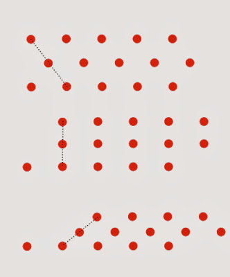
Centroid-coordinated tessellations

Inequivalent affine transformations can produce identical results when they act on an array of unlabeled points. In this case, shear plus one-dimensional magnification (not show) acts like the identity transformation.

Coordinated tessellations occur in two practical problems that arise in relation to telescopic heliostats: first, the problem of simultaneously packing the primary mirrors (as seen from the sun) and the secondary mirrors (as seen from the beam-down optics;) and second, the problem of simultaneously packing the primary and secondary lenses in the divergence reshapers that are a necessary part of the beam-down optics.

Definition: Two tessellations of the plane are centroid-coordinated when they are overlain such that each tile has its centroid coincident with that of a tile in the other tessellation.

Non-trivial centroid coordination (when the two tessellations are not identical) is possible because, when acting on an array of unlabeled points (like the tile centroids of a tessellation,) inequivalent affine transformations may act identically. In other words, if we apply two inequivalent affine transformations to a tessellation we will generate two different tessellations as a result, but applying the same two transformations to an array of unlabeled points (e.g., the tile centroids) may give identical results.

For example, consider a set of tile centroids that are arrayed in a brick-layer's "stretcher bond" pattern as in the top arrangement in the figure above. Shearing this array of points takes them out of proper stretcher bond order (middle arrangement)—but shearing them some more can bring them back into a new stretcher bond order (bottom arrangement.) The height of the bricks is now too short, but that is easily corrected by composition with another affine transformation that is a magnification in one dimension only. This newly contrived composite transformation and the identity transformation now act identically on the array of tile centroids, but differently on the tessellation. The two tessellations generated by the transforms are centroid-coordinated.

The shearing-plus-magnification transform we need is just a shearing in which only x-coordinates are altered. The magic angles that work for this shearing, are ones for which dots translate in the x-dimension by an integer multiple, n, of the inter-dot distance, d.

For the stretcher bond pattern with shearing angle θ:

(d/ √3) * tanθ = n * d,

tanθ = n √3.


For the Cartesian grid pattern

d * tanθ = n * d,

tanθ = n.


Rectangle tesellations


A centroid coordination of a tessellation of squares with a tessellation of 4:1 rectangles. In this kind of arrangement, the centroids are arranged along oblique lines that rise one rectangle's height in traveling the other rectangle's width. Both kinds of rectangles have the same area.

When two rectangle tessellations, a and b, are centroid coordinated, their heights, ha and hb, and widths, wa and wb, are related by two integers, m and n. Taking the rectangles of type a to be the taller, and those of type b the wider:

ha = m hb

wb = n wa.

But the rectangle areas are equal:

ha * wa = hb * wb

so,

m hb * wa = hb * n wa

m = n.

This is just the commonsense notion that, if two rectangles have the same area, and one is a factor f times taller, it must also be a factor of f times narrower. For rectangles in centroid-coordinated tessellations the constraint is added that f must be an integer.

Since the affine transformation of a polygon’s centroid is the centroid of the affine transformation of the polygon, once we have found a pair of centroid-coordinated tessellations, applying an affine transformation to both will generate a new pair of centroid-coordinated tessellations. For centroid-coordinated rectangle tessellations, their integer characteristic m is not altered by affine transformation, but we can vary the size and aspect ratio one species of rectangle just as we please by choosing different values of linear magnification in each dimension.

For example, we can choose an affine transformation that turns one species of rectangles into squares. Therefore, every pair of centroid-coordinated rectangle tessellations is related by an affine transformation to another pair of centroid-coordinated rectangle tessellations having the same value of m, but where one species of rectangles are squares and the aspect ratio of the other species of rectangles is m squared.

For example, in designing a divergence reshaper having optical inputs and outputs that are delimited by solid angles of rectangular shape, if the output solid angle must be square in shape, the input solid angle must be a rectangle of aspect ratio m2, where m is an integer.

Friday, November 1, 2013

Low-aiming, target points, and optimization

Cross-section of an array of telescopic heliostats showing the target point for all heliostats lying at the same azimuth to the field center. The field radius is 14 times the height of the beam-down optics—about twice the comparable ratio for conventional heliostats.


Aiming slightly low in the outer portion of the heliostat field, and slightly high in the inner portion of the field, offers the advantage of making the focal zone more compact. This variable aiming can be idealized as aiming all the heliostats that lie on the same azimuth from the origin toward a single target point behind the focal zone. When heliostats are targeted in this way, the locus of the geometric constraint—the ideal shape of the beam-down optics—is no longer a family of confocal parabolas, instead it is a family of ellipses having as their foci the target point and the oculus center.

Whatever happens near the inner radius of the field is of minor importance due to the relatively small number of heliostats involved. On the other hand, what happens with heliostats near the outer radius of the field is important because there are the most numerous rows of heliostats.

Low-aiming of heliostats at the periphery can be carried too far. With constant aiming, the lowest ray in the beam from a secondary rises at only beta/2 (1:36 with 6x telescopic heliostats.) Lowering aim by a mere beta/2 would send the lowest rays traveling horizontally—guaranteeing that they would hit the back of another secondary. In fact, any lowering of the aiming angle will entail either some blocking by other secondaries (should we keep the primaries close-packed) or a decrease in land utilization (if we space the primaries out.) An optimized system will always have a bit of every possible kind of loss: all the possible losses come out to play in the big trade-off game. For the purpose of a simple baseline design we can be arbitrary: we will insist on zero blocking loss, but we will permit the land utilization in the outermost row to fall to 2/3.


The circles are the primary mirrors viewed from above; the ellipses are the shadows cast on a horizontal plane by the secondaries when illuminated from the direction of the lowest ray in there beam. 
In a system with 6x telescopic heliostats, the beam spread is 3°, and the nominal beaming angle is 3.1°. That leaves the lowest rays in the beam directed 1.6° above horizontal, or a run-over-rise of 36:1. The ellipses in the figure above are 9:1, they would need to be elongated to 36:1, but still with the same surface area, to represent the design condition. Aiming lower while keeping blocking at zero means that the ellipses must be further elongated, but this time the dimension of the minor axis is kept constant and the surface area is allowed to increase. The surface area of the circles (which represent the primary mirrors) are not allowed to change when we aim lower because we are using the same design of heliostats over the whole field. Therefore, the area increase of the ellipses associated with low-aiming is balanced by extra empty space between primaries.

At the last row we allow 2/3 land utilization, meaning that low-aiming is permitted to increase the surface area of the ellipses by 50%: their aspect ratio can increase from 36:1 to 54:1. So, at the last row, the lowest ray can have a run-over-rise of 54:1, which is an elevation angle of 1.1°. Recalling that the beam spread is 3°, the middle ray will have an elevation angle of 2.6°, or a run-over-rise of 22:1; the top ray will have an elevation angle of 4.1°, or a run-over-rise of 14 (putting that in a short hand, the outer heliostat operates at: 14-22-54, in run-over-rise numbers, which are also the reciprocals of the elevation angles measured in radians.) By comparison, a heliostat at its design condition operates at 12.4-18.5-36.

The unique row of heliostats that operates with both design condition aiming and chock-a-block packing should be located somewhere near the median radius of the field (outer radius / sqrt 2.) The top image diagrams such a system. The target point turns out to be little bit higher than the beam-down optics, and about one field radius behind the center of the field.

Calculation of target position, where γ is the ratio of design beaming angle, β, to the beaming angle, βe at the outer radius, ro; and r is the target point's radial distance from the center of the field. Heliostats operating at the design condition are assumed to lie at the median radius (0.707 * ro) from the center of the field. In this example γ = 22/18.5 = 1.19, so r/ro = 0.84. The height of the target point is then ro * (1 + 0.84) / 22 = .084 ro .

The run-over-rise number for the top ray of the outermost heliostats—in this example, 14—is also the ratio of the field radius to the tower height (or height at the top of the beam-down optics.) Telescopic heliostats give twice the value for conventional heliostat fields, but with much better land utilization.