Showing posts with label tower height. Show all posts

Tuesday, February 11, 2014

Solar Highbeams Target Design compared with Crescent Dunes

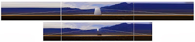
The Solar Highbeams Target Design compared with the Crescent Dunes Solar Energy Project. Underlying image quoted from Google Maps.


Table comparing the Solar Highbeams Target Design with the Crescent Dunes Solar Energy Project.
The ratings assume that the annual average power per mirror area of Crescent Dunes (51 W/m2) can also be achieved in the target design. Maximum boiler temperature at Crescent Dunes is 565 °C (1050 °F).

Advanced steam turbine technology: plant efficiency vs. steam temperature. Image quoted from EPRI, "Materials Technology to Enable High-Efficiency Advanced Ultrasupercritical (A-USC) Steam Power Plants"

The plot of plant efficiency vs. steam temperature above suggests that increasing steam temperature from Crescent Dunes' 565 °C (1050 °F) to an A-USC (advanced ultra supercritical) turbine's 760 °C (1400 °F), would increase plant output by about a factor of 46.5/42.3 = 1.10. That gives some leeway in rating the Solar Highbeams Target Design at 1 GW though its atmospheric turbidity losses will be greater than Crescent Dunes', and possibly its rather different shading and blocking losses will be greater as well. Eventually, thermophotovoltaic (TPV) conversion may offer even higher efficiencies.

Wednesday, January 29, 2014

Ten things we know about telescopic heliostats

They're necessary. Ground loss—the quantity of sunlight falling between heliostats—is atrocious in current generation CSP's. Obvious in a satellite view is the fact that far more sunlight is reaching the ground than the mirrors. Land requirements are being tripled! The Second Law of Thermodynamics decrees that a heliostat without ground loss must act like a telescope, i.e., it must increase the divergence of the reflected beam while maintaining collimation (parallel rays map to parallel rays.)

Telescopic heliostats must have two mirrors. No fewer than two lenses (objective and eyepiece) compose a telescope.

Optimum power is about 6X. Magnifying the sun's disk, which is 0.5° in diameter, six times makes an intensified, but still collimated beam (or highbeam) that can be aimed at an elevation angle as small as its own diameter, 3.0°. That condition minimizes the height of the central, beam-down optics or lamp.

Central, beam-down optics are necessary. At 3.0° divergence, the highbeams are simply too spread to form a high quality focus without another optical stage.

The lamp (central beam-down optics)—shaped something like an overturned apple—will be only 60% as tall as a power tower on the same field. Larger heliostat fields are thus made practical.

The objective needs to move, the eyepiece doesn't. The objective (primary) mirror can redirect sunlight vertically to a fixed focus: the much smaller eyepiece (secondary) mirror gets to sit right there.

The objective needs to have its optical profile continuously fine-tuned to the sun's changing zenith distance. To first order, the adaptation needed is simply a thin-shell bending of the mirror.

Telescopic heliostats move in concert. The only real difference between two telescopic heliostats in a field is the azimuth aiming of their eyepieces. All the objectives could be mechanically ganged.

At at 0.70 mirror/land ratio, telescopic heliostats can be sited with negligible blocking. Surprisingly, the presence of the eyepieces adds no complication at all to heliostat siting when a phyllotaxis-based algorithm is used. The packing density achieved is more than three times that of a conventional heliostat field.

These improvements in field size and field packing make it practical to design a replicable 1 GW, 75% capacity-factor, standard solar plant covering one quarter-township (9 square miles) in the southwest U.S. The central lamp, about 190 m high, would be only 20% taller than current-generation power towers. Goodbye coal!


Wednesday, January 22, 2014

Five advantages of the Solar Highbeams Project

For the same central height, a solar highbeams plant harvests than three times the land area.  (Underlying image of  Ivanpah Solar Electric Generating System quoted from the Washington Post.)


A solar highbeams plant catches more than three times the sunlight from an acre of land. (Aerial photo of  Ivanpah Solar Electric Generating System quoted from Google Maps.)


Solar high beams heliostats all move identically; this allows them to be mechanically ganged.


The focal zone in a solar highbeams plant is at ground level; this makes large-scale storage, power conversion, and industrial uses practical. (Glass furnace image quoted from Mirion Technologies.)


The rabbit advantage: because each solar highbeams power plant is a glass-making furnace as well, it can make the glass for additional plants. Making the glass for two more plants would delay power operations only a matter of months.

Wednesday, November 13, 2013

Beam-down optics designed with coextensive penumbras

Design for the optics at the center of a field of telescopic heliostats. Beam from farthest heliostat (blue) and nearest heliostat (yellow.) Lamp walls with elliptical profile (red,) thermal cap (yellow,) thermal wall (orange.) Penumbras of the field and of the thermal cap and thermal wall are adjusted to be coextensive.

Cross-section of the entire heliostat field (green) with lamp (red) and target point (yellow.)
Following the advice of the previous post, this design has coextensive penumbras. That is, the penumbra of the thermal cap (the upper portion of the radiant field lying between black and the sharp bends in the fringes) is coextensive along the surface of the lamp (red) with the upper penumbra of the field (the region between the blue rays coming from the farthest heliostat;) and the penumbra of the thermal wall (the lower portion of the radiant field between black and the sharp bends in the fringes) is coextensive along the surface of the lamp with the lower penumbra of the field (the region between the yellow rays coming from the nearest heliostat.)

This design has:

field radius = 1
inner field radius = 0.2
telescopic heliostat power = 6x
oculus radius = 0.0058
thermal cap radius = 2.1 * oculus radius
zenith distance to edge of cap = pi/3.6
thermal wall radius =2.7 * oculus radius
zenith distance to top of wall = pi/2.33
lamp height = 0.060

Thursday, November 7, 2013

Comparison of conventional and telescopic heliostat fields at the same tower height

For the same height at the central receiver or beam-down optics, a telescopic heliostat field will have about twelve times the power rating of a conventional heliostat field. About a factor of three comes from increased field radius, and a about factor of four from improved land utilization.
For the same height at the central receiver or beam-down optics, a field of telescopic heliostats has about twelve times the power rating of a field of conventional heliostats. Of this factor of twelve, about a factor of three comes from increased field radius (the field radius is 14 times the tower height as opposed to 9 times) and about a factor of four comes from covering the land more densely with heliostat mirrors (81% mirror fill as opposed to 17%.)

Take for example the 160 m tower height of the solar plant now under construction in Crescent Dunes, Nevada. A telescopic heliostat field with beam-down optics topping out at a height of 160 m would have a heliostat field radius of 2225 m, and 81% mirror fill, giving an approximately 1.3 GW solar plant instead of the 110 MW the plant being built at Crescent Dunes. Significantly, with telescopic heliostats, this full-sized power plant would be ground-mounted rather than on a tower.

The radius/tower ratio of 14 for a field of telescopic heliostsats was calculated in a previous post.

The mirror fill of 81% for a field of telescopic heliostats was estimated as follows.

The packing efficiency of circles in a hexagonal arrangement on the plane is 0.907. Taking the mirror fill in the solid phase of the heliostat field to be 90%, the previous calculations assumed the mirror fill in the outermost ring of heliostats would be 0.6 of this value or 54%, so, on average, the mirror fill in the gas phase of the heliostat field will be roughly the mean of 54% and 90%, or 72%. Since the gas and solid phases of the heliostat field have equal areas, overall the mirror fill is the mean of 90% and 72%, or 81%.

Friday, November 1, 2013

Low-aiming, target points, and optimization

Cross-section of an array of telescopic heliostats showing the target point for all heliostats lying at the same azimuth to the field center. The field radius is 14 times the height of the beam-down optics—about twice the comparable ratio for conventional heliostats.


Aiming slightly low in the outer portion of the heliostat field, and slightly high in the inner portion of the field, offers the advantage of making the focal zone more compact. This variable aiming can be idealized as aiming all the heliostats that lie on the same azimuth from the origin toward a single target point behind the focal zone. When heliostats are targeted in this way, the locus of the geometric constraint—the ideal shape of the beam-down optics—is no longer a family of confocal parabolas, instead it is a family of ellipses having as their foci the target point and the oculus center.

Whatever happens near the inner radius of the field is of minor importance due to the relatively small number of heliostats involved. On the other hand, what happens with heliostats near the outer radius of the field is important because there are the most numerous rows of heliostats.

Low-aiming of heliostats at the periphery can be carried too far. With constant aiming, the lowest ray in the beam from a secondary rises at only beta/2 (1:36 with 6x telescopic heliostats.) Lowering aim by a mere beta/2 would send the lowest rays traveling horizontally—guaranteeing that they would hit the back of another secondary. In fact, any lowering of the aiming angle will entail either some blocking by other secondaries (should we keep the primaries close-packed) or a decrease in land utilization (if we space the primaries out.) An optimized system will always have a bit of every possible kind of loss: all the possible losses come out to play in the big trade-off game. For the purpose of a simple baseline design we can be arbitrary: we will insist on zero blocking loss, but we will permit the land utilization in the outermost row to fall to 2/3.


The circles are the primary mirrors viewed from above; the ellipses are the shadows cast on a horizontal plane by the secondaries when illuminated from the direction of the lowest ray in there beam. 
In a system with 6x telescopic heliostats, the beam spread is 3°, and the nominal beaming angle is 3.1°. That leaves the lowest rays in the beam directed 1.6° above horizontal, or a run-over-rise of 36:1. The ellipses in the figure above are 9:1, they would need to be elongated to 36:1, but still with the same surface area, to represent the design condition. Aiming lower while keeping blocking at zero means that the ellipses must be further elongated, but this time the dimension of the minor axis is kept constant and the surface area is allowed to increase. The surface area of the circles (which represent the primary mirrors) are not allowed to change when we aim lower because we are using the same design of heliostats over the whole field. Therefore, the area increase of the ellipses associated with low-aiming is balanced by extra empty space between primaries.

At the last row we allow 2/3 land utilization, meaning that low-aiming is permitted to increase the surface area of the ellipses by 50%: their aspect ratio can increase from 36:1 to 54:1. So, at the last row, the lowest ray can have a run-over-rise of 54:1, which is an elevation angle of 1.1°. Recalling that the beam spread is 3°, the middle ray will have an elevation angle of 2.6°, or a run-over-rise of 22:1; the top ray will have an elevation angle of 4.1°, or a run-over-rise of 14 (putting that in a short hand, the outer heliostat operates at: 14-22-54, in run-over-rise numbers, which are also the reciprocals of the elevation angles measured in radians.) By comparison, a heliostat at its design condition operates at 12.4-18.5-36.

The unique row of heliostats that operates with both design condition aiming and chock-a-block packing should be located somewhere near the median radius of the field (outer radius / sqrt 2.) The top image diagrams such a system. The target point turns out to be little bit higher than the beam-down optics, and about one field radius behind the center of the field.

Calculation of target position, where γ is the ratio of design beaming angle, β, to the beaming angle, βe at the outer radius, ro; and r is the target point's radial distance from the center of the field. Heliostats operating at the design condition are assumed to lie at the median radius (0.707 * ro) from the center of the field. In this example γ = 22/18.5 = 1.19, so r/ro = 0.84. The height of the target point is then ro * (1 + 0.84) / 22 = .084 ro .

The run-over-rise number for the top ray of the outermost heliostats—in this example, 14—is also the ratio of the field radius to the tower height (or height at the top of the beam-down optics.) Telescopic heliostats give twice the value for conventional heliostat fields, but with much better land utilization.

Thursday, October 31, 2013

Telescopic heliostats: designing heliostats as if thermodynamics mattered

Sunlight falls to the ground in an array of conventional heliostats—and the central tower is unnecessarily tall—because thermodynamics is ignored in the optical design. Since any optical system could be handling thermal radiation, all optical design is constrained by the Second Law of Thermodynamics.


It's not nice to fool Mother Nature. Redirecting sunlight toward a lower angular elevation is a sneaky way to increase its flux—therefore the Second Law of Thermodynamics demands that the light's divergence increase as well. In plain terms, thermodynamics permits us to make the sun look closer, but not hotter.  A high-performance heliostat must be an optical device that increases the flux and divergence of sunlight while keeping parallel rays parallel, in other words, a telescope.


The twin beams of light emerging from these 7x binoculars focussed at infinity and pointed at the sun are quite collimated, even though the solar flux has been increased about 49 times. Calculations indicate that 6x magnification would be optimal for a telescopic heliostat.


The Cassegrain configuration as it is usually described—a parabolic primary with a hyperbolic secondary—is not actually a telescope until an eyepiece is added. A secondary mirror having instead a parabolic profile would move the focal point to infinity, and thus serve as the eyepiece.

Thursday, October 24, 2013

Optimizing telescopic heliostat arrays

Whoops! Looks like most of the sunlight is hitting the ground.

Conventional heliostat arrays have about 33% land utilization—most of the available sunlight strikes the ground! The angular elevation of the top of the tower as viewed from the farthest heliostat is about 7.4 degrees, or a run-over-rise of about 7.8. Telescopic heliostats can do better on both accounts.

Economic optimization of a heliostat array is a Godzilla of a problem requiring full cost data, full knowledge of the operation of the rest of the plant, and full knowledge of the solar resource. A simpler option is available for telescopic heliostats: we can simply design for negligible loss of available sunlight. (This is not an option with conventional heliostats because flat mirrors start blocking each others' view of the target long before they are packed closely enough to collect most of the available light.)

"Designing for negligible loss of available sunlight" in practice means packing the primaries closely and designing the secondaries on the basis of their lowest ray (i.e., the ray most likely to be intercepted by the back of another secondary.)

Closely packed primary mirrors shade about 90% of the land area in the worst case (sun at zenith.) Utilization improves as the sun lowers and the primary mirrors tilt up.

It is also necessary to avoid blocking (redirected light hitting the back of secondaries) if we want to avoid wasting light. We will consider a particular case.

Consider a telescope of linear magnification six. It intensifies sunlight 36 times while increasing its angular divergence by a factor of six. The beam spread of natural sunlight is 0.5°, so the sunlight emerging from the eyepiece of a 6x telescope will have a beam spread of 3°. To accomplish that increase in divergence requires the secondary mirror to be six times closer to the focussed image of the sun than the primary mirror that formed the image. The secondary mirror is tilted about 45° to redirect vertically upward sunlight to nearly horizontal, so it will have an oblong planform, but viewed from directly above (or from the distant central tower), it appears nearly circular, and this circle has one sixth the diameter of the primary mirror.

The now familiar figure below can represent this situation if the ellipses (which as-drawn have 9:1 aspect ratio) are redrawn to a 36:1 aspect ratio while keeping their area the same. Recall that the ellipses in this diagram represent the shadows cast on the ground when the secondaries are illuminated by an imaginary light source located at a design point on the beam-down optics. Since we are interested in minimizing blocking, this design point must be where the lowest rays from the secondaries converge—not their central rays. The 36:1 shadows cast by essentially circular objects are evidence that the imaginary light source is at a run-over-rise of 36:1, or an angular elevation of 1.6°. To this must be added the full 3° beam spread of the light emitted by the secondaries, placing the top of the beam-down optics at an angular elevation of 4.6°, a run-over-rise of 12.4.

Thus, for a given tower height, a telescopic heliostat array has about 1.59 times the radius and 2.5 times the area of a conventional heliostat array. It also has about three times the land utilization, giving overall a plant rating about 7.5 times that of a conventional system.


Primary mirrors can be close packed in a telescopic heliostat array without causing the secondaries to block each other.