Tuesday, November 12, 2013

Approximate dimensions of the beam-down optics

Dimensions of the beam-down optics for a field of 6x telescopic heliostats. The radius of the heliostat field is taken as 1.

Based on the heliostat targeting described in an earlier post, here is a rough approximation of the dimensions of the beam-down optics, the optics in the center of the heliostat field that redirect concentrated sunlight toward the furnace opening or oculus. Taking the radius of the heliostat field to be 1, then, as found in the earlier post, the height of the optics is 0.071. Assuming the beam-down optics, when viewed from the furnace opening (oculus,) fill all but a 30°-zenith distance of the sky, and approximating the beam-down optics as a cylinder, the cylinder diameter is 0.082. If sunlight filled the entire sky at the oculus, geometric concentration would be 40,000x. The 30°-zenith distance hole in the sky reduces this to 30,000x, giving an oculus radius of 1/√30,000 = 0.0058, or a diameter of 0.012. The heliostat field radius is 173x the oculus radius.

The cylinder diameter is about 6.8x the oculus diameter, and the cylinder height is about 5.9x the occults diameter. The cylinder has an area of pi * 0.082 * 0.071, while the heliostat field has an area of pi, giving a geometric concentration on the beam-down optics of 172.

In summary, geometric concentration factors are approximately:

telescopic heliostat primary: 1x

telescopic heliostat secondary: 36x

beam-down optics: 172x

oculus: 30,000x

From the earlier post, the aiming target is 0.84 behind the center of the field, and at a height of 0.084.

Friday, November 8, 2013

Center-coordinated packings of circles and ellipses

Certain "magic" aspect ratios allow a close packing of ellipses to be center-coordinated with a hexagonal close-packing of circles. The aspect ratios that work are central polygonal numbers; in this case 3.
Center-coordinated tessellations or packings are relevant in two ways to telescopic heliostats: they describe a way to simultaneously close-pack the primary mirrors (as seen from the sun's perspective) and the secondary mirrors (as seen from the perspective of the beam-down optics,) and they also describe ways that the lenslet arrays in the beam-down optics can be paired in registration with each other. A previous post showed that a tessellation of rectangles can be centroid-coordinated with a tessellation of squares if the aspect ratio of the rectangle is drawn from the set of integers. This post considers packings of ellipses that are center-coordinated with hexagonal close-packings of circles.

In the figure above, an affine transformation that transforms the bold equilateral triangle into the dashed green triangle will also transform the packed circles into the packed ellipses, and use the same set of points for centers. If the bold triangle, together with its decoration of three circular arcs, is considered a truchet tile that generates the packing of circles, shearing and stretching this truchet triangle (along with its decorations) yields a new truchet triangle that generates the packing of ellipses.

The example illustrated in the figure is just the first in a series of possibilities: for instance, we could have translated the apex of the triangle rightward two steps instead of just one. Taking the sides of the equilateral triangle to be unit length, the transformed left side of the triangle has length √3, and this is identically the length of the major axis of the ellipses. Since the area of the ellipses must be equal to that of the original circles (in order to give a center-coordinated packing) the minor axis of the ellipses is therefore 1/√3, and the aspect ratio of the ellipses is 3—or simply the square of the length of the longest side of the new triangle. From the Pythagorean Theorem, the square of that length is, where n is the number of steps the apex has translated:

(1/2 + n)2 + (√3/2)2

= 1/4 + n + n2 + 3/4

= n + n2 + 1

= {1, 3, 7, 13, 21, 31, 43, 57, 73, 91...}.

These numbers are known as the central polygonal numbers. 

Therefore, a close-packing of ellipses can be center-coordinated with a hexagonal close-packing of circles provided the aspect ratio of the ellipses is drawn from the set of central polygonal numbers.

The angle of the major axis is rotated by an angle θ from vertical where

θ = arctan((1 + 2n)/√3)).

Any two close-packings of ellipses can be center-coordinated provided that the two varieties of ellipses have equal areas and their respective aspect ratios are drawn from the central polygonal numbers. As mentioned in the previous post, given a centroid-coordinated pattern, it can be transformed by any affine transformation into another centroid-coordinated pattern. In particular, ellipse/ellipse patterns can be transformed to a center-coordinated pattern where one variety of the ellipses are circles. Thus the circle/ellipse patterns are the fundamental ones, the rest can be generated from these by affine transformation.

Center-coordinated ellipse and circle packings: aspect ratio = 3.


Center-coordinated ellipse and circle packings: aspect ratio = 7.


Center-coordinated ellipse and circle packings: aspect ratio = 13. 


Center-coordinated ellipse and circle packings: aspect ratio = 21. 

Thursday, November 7, 2013

Comparison of conventional and telescopic heliostat fields at the same tower height

For the same height at the central receiver or beam-down optics, a telescopic heliostat field will have about twelve times the power rating of a conventional heliostat field. About a factor of three comes from increased field radius, and a about factor of four from improved land utilization.
For the same height at the central receiver or beam-down optics, a field of telescopic heliostats has about twelve times the power rating of a field of conventional heliostats. Of this factor of twelve, about a factor of three comes from increased field radius (the field radius is 14 times the tower height as opposed to 9 times) and about a factor of four comes from covering the land more densely with heliostat mirrors (81% mirror fill as opposed to 17%.)

Take for example the 160 m tower height of the solar plant now under construction in Crescent Dunes, Nevada. A telescopic heliostat field with beam-down optics topping out at a height of 160 m would have a heliostat field radius of 2225 m, and 81% mirror fill, giving an approximately 1.3 GW solar plant instead of the 110 MW the plant being built at Crescent Dunes. Significantly, with telescopic heliostats, this full-sized power plant would be ground-mounted rather than on a tower.

The radius/tower ratio of 14 for a field of telescopic heliostsats was calculated in a previous post.

The mirror fill of 81% for a field of telescopic heliostats was estimated as follows.

The packing efficiency of circles in a hexagonal arrangement on the plane is 0.907. Taking the mirror fill in the solid phase of the heliostat field to be 90%, the previous calculations assumed the mirror fill in the outermost ring of heliostats would be 0.6 of this value or 54%, so, on average, the mirror fill in the gas phase of the heliostat field will be roughly the mean of 54% and 90%, or 72%. Since the gas and solid phases of the heliostat field have equal areas, overall the mirror fill is the mean of 90% and 72%, or 81%.

Mirror/land ratios in solar power tower generating stations


Based on Google imagery, the heliostat field of Ivanpah 1 is very nearly a square, 1995 m on a side, with three corner truncations, giving a heliostat field land area of about 3,800,000 square meters. This unit has 53,527 heliostats each with a mirror area of 15 square meters, giving a total mirror area of 803,000 square meters. The mirror/land ratio is 0.21.


Based on Google imagery, the heliostat field of the Crescent Dunes Solar Energy Project is very nearly circular, with a diameter of about 2804 m, giving a heliostat field land area of about 6,200,000 square meters. This unit will have 17,170 heliostats, each carrying 62.4 square meters of mirror, giving a total mirror area of 1,070,000 square meters. The mirror/land ratio is 0.17.

The mean radius of the heliostat field (the radius of a circle having the same area as the field) is 1100 m for Ivanpah 1; 1402 m for Crescent Dunes. The tower heights are 140 m and 160 m respectively, giving mean field radius to tower height ratios of 7.9 and 8.8.

Tuesday, November 5, 2013

Optimizing heliostat arrays

Every optimized heliostat array embodies a phase transition between a packed inner zone (solid phase) and a dispersed outer zone (gas phase.)

When a heliostat array is optimized, heliostats arrange themselves into two phases. Close to the tower, heliostats are closely packed (the solid phase.) Far from the tower, heliostats are spaced apart (the gas phase.) The gas phase wastes land area; the solid phase wastes thermodynamic availability because these heliostats are too close to the target—from the receiver's point of view the sun's image fails to fill the mirror.  Only at the boundary between these two phases (the condensation line) do heliostats work with maximal return on investment, wasting neither land nor thermodynamic availability.

That the heliostats at the boundary are working optimally is evidenced by the fact that, given the opportunity to spread out a little to improve performance, they choose not to spread out at all!

Monday, November 4, 2013

Centroid-coordinated tessellations

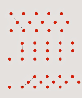
Inequivalent affine transformations can produce identical results when they act on an array of unlabeled points. In this case, shear plus one-dimensional magnification (not show) acts like the identity transformation.

Coordinated tessellations occur in two practical problems that arise in relation to telescopic heliostats: first, the problem of simultaneously packing the primary mirrors (as seen from the sun) and the secondary mirrors (as seen from the beam-down optics;) and second, the problem of simultaneously packing the primary and secondary lenses in the divergence reshapers that are a necessary part of the beam-down optics.

Definition: Two tessellations of the plane are centroid-coordinated when they are overlain such that each tile has its centroid coincident with that of a tile in the other tessellation.

Non-trivial centroid coordination (when the two tessellations are not identical) is possible because, when acting on an array of unlabeled points (like the tile centroids of a tessellation,) inequivalent affine transformations may act identically. In other words, if we apply two inequivalent affine transformations to a tessellation we will generate two different tessellations as a result, but applying the same two transformations to an array of unlabeled points (e.g., the tile centroids) may give identical results.

For example, consider a set of tile centroids that are arrayed in a brick-layer's "stretcher bond" pattern as in the top arrangement in the figure above. Shearing this array of points takes them out of proper stretcher bond order (middle arrangement)—but shearing them some more can bring them back into a new stretcher bond order (bottom arrangement.) The height of the bricks is now too short, but that is easily corrected by composition with another affine transformation that is a magnification in one dimension only. This newly contrived composite transformation and the identity transformation now act identically on the array of tile centroids, but differently on the tessellation. The two tessellations generated by the transforms are centroid-coordinated.

The shearing-plus-magnification transform we need is just a shearing in which only x-coordinates are altered. The magic angles that work for this shearing, are ones for which dots translate in the x-dimension by an integer multiple, n, of the inter-dot distance, d.

For the stretcher bond pattern with shearing angle θ:

(d/ √3) * tanθ = n * d,

tanθ = n √3.


For the Cartesian grid pattern

d * tanθ = n * d,

tanθ = n.


Rectangle tesellations


A centroid coordination of a tessellation of squares with a tessellation of 4:1 rectangles. In this kind of arrangement, the centroids are arranged along oblique lines that rise one rectangle's height in traveling the other rectangle's width. Both kinds of rectangles have the same area.

When two rectangle tessellations, a and b, are centroid coordinated, their heights, ha and hb, and widths, wa and wb, are related by two integers, m and n. Taking the rectangles of type a to be the taller, and those of type b the wider:

ha = m hb

wb = n wa.

But the rectangle areas are equal:

ha * wa = hb * wb

so,

m hb * wa = hb * n wa

m = n.

This is just the commonsense notion that, if two rectangles have the same area, and one is a factor f times taller, it must also be a factor of f times narrower. For rectangles in centroid-coordinated tessellations the constraint is added that f must be an integer.

Since the affine transformation of a polygon’s centroid is the centroid of the affine transformation of the polygon, once we have found a pair of centroid-coordinated tessellations, applying an affine transformation to both will generate a new pair of centroid-coordinated tessellations. For centroid-coordinated rectangle tessellations, their integer characteristic m is not altered by affine transformation, but we can vary the size and aspect ratio one species of rectangle just as we please by choosing different values of linear magnification in each dimension.

For example, we can choose an affine transformation that turns one species of rectangles into squares. Therefore, every pair of centroid-coordinated rectangle tessellations is related by an affine transformation to another pair of centroid-coordinated rectangle tessellations having the same value of m, but where one species of rectangles are squares and the aspect ratio of the other species of rectangles is m squared.

For example, in designing a divergence reshaper having optical inputs and outputs that are delimited by solid angles of rectangular shape, if the output solid angle must be square in shape, the input solid angle must be a rectangle of aspect ratio m2, where m is an integer.

Friday, November 1, 2013

Low-aiming, target points, and optimization

Cross-section of an array of telescopic heliostats showing the target point for all heliostats lying at the same azimuth to the field center. The field radius is 14 times the height of the beam-down optics—about twice the comparable ratio for conventional heliostats.


Aiming slightly low in the outer portion of the heliostat field, and slightly high in the inner portion of the field, offers the advantage of making the focal zone more compact. This variable aiming can be idealized as aiming all the heliostats that lie on the same azimuth from the origin toward a single target point behind the focal zone. When heliostats are targeted in this way, the locus of the geometric constraint—the ideal shape of the beam-down optics—is no longer a family of confocal parabolas, instead it is a family of ellipses having as their foci the target point and the oculus center.

Whatever happens near the inner radius of the field is of minor importance due to the relatively small number of heliostats involved. On the other hand, what happens with heliostats near the outer radius of the field is important because there are the most numerous rows of heliostats.

Low-aiming of heliostats at the periphery can be carried too far. With constant aiming, the lowest ray in the beam from a secondary rises at only beta/2 (1:36 with 6x telescopic heliostats.) Lowering aim by a mere beta/2 would send the lowest rays traveling horizontally—guaranteeing that they would hit the back of another secondary. In fact, any lowering of the aiming angle will entail either some blocking by other secondaries (should we keep the primaries close-packed) or a decrease in land utilization (if we space the primaries out.) An optimized system will always have a bit of every possible kind of loss: all the possible losses come out to play in the big trade-off game. For the purpose of a simple baseline design we can be arbitrary: we will insist on zero blocking loss, but we will permit the land utilization in the outermost row to fall to 2/3.


The circles are the primary mirrors viewed from above; the ellipses are the shadows cast on a horizontal plane by the secondaries when illuminated from the direction of the lowest ray in there beam. 
In a system with 6x telescopic heliostats, the beam spread is 3°, and the nominal beaming angle is 3.1°. That leaves the lowest rays in the beam directed 1.6° above horizontal, or a run-over-rise of 36:1. The ellipses in the figure above are 9:1, they would need to be elongated to 36:1, but still with the same surface area, to represent the design condition. Aiming lower while keeping blocking at zero means that the ellipses must be further elongated, but this time the dimension of the minor axis is kept constant and the surface area is allowed to increase. The surface area of the circles (which represent the primary mirrors) are not allowed to change when we aim lower because we are using the same design of heliostats over the whole field. Therefore, the area increase of the ellipses associated with low-aiming is balanced by extra empty space between primaries.

At the last row we allow 2/3 land utilization, meaning that low-aiming is permitted to increase the surface area of the ellipses by 50%: their aspect ratio can increase from 36:1 to 54:1. So, at the last row, the lowest ray can have a run-over-rise of 54:1, which is an elevation angle of 1.1°. Recalling that the beam spread is 3°, the middle ray will have an elevation angle of 2.6°, or a run-over-rise of 22:1; the top ray will have an elevation angle of 4.1°, or a run-over-rise of 14 (putting that in a short hand, the outer heliostat operates at: 14-22-54, in run-over-rise numbers, which are also the reciprocals of the elevation angles measured in radians.) By comparison, a heliostat at its design condition operates at 12.4-18.5-36.

The unique row of heliostats that operates with both design condition aiming and chock-a-block packing should be located somewhere near the median radius of the field (outer radius / sqrt 2.) The top image diagrams such a system. The target point turns out to be little bit higher than the beam-down optics, and about one field radius behind the center of the field.

Calculation of target position, where γ is the ratio of design beaming angle, β, to the beaming angle, βe at the outer radius, ro; and r is the target point's radial distance from the center of the field. Heliostats operating at the design condition are assumed to lie at the median radius (0.707 * ro) from the center of the field. In this example γ = 22/18.5 = 1.19, so r/ro = 0.84. The height of the target point is then ro * (1 + 0.84) / 22 = .084 ro .

The run-over-rise number for the top ray of the outermost heliostats—in this example, 14—is also the ratio of the field radius to the tower height (or height at the top of the beam-down optics.) Telescopic heliostats give twice the value for conventional heliostat fields, but with much better land utilization.